the Creative Commons Attribution 4.0 License.
the Creative Commons Attribution 4.0 License.
 | 27 May 2020
Ice shelf rift propagation: stability, three-dimensional effects, and the role of marginal weakening
Bradley Paul Lipovsky
Understanding the processes that govern ice shelf extent is important to improving estimates of future sea-level rise. In present-day Antarctica, ice shelf extent is most commonly determined by the propagation of through-cutting fractures called ice shelf rifts. Here, I present the first three-dimensional analysis of ice shelf rift propagation. I model rifts using the assumptions of linear elastic fracture mechanics (LEFM). The model predicts that rifts may be stabilized (i.e., stop propagating) when buoyant flexure results in the partial contact of rift walls. This stabilizing tendency may be overcome, however, by processes that act in the ice shelf margins. In particular, loss of marginal strength, modeled as a transition from zero tangential displacement to zero tangential shear stress, is shown to favor rift propagation. Rift propagation may also be triggered if a rift is carried with the ice flow (i.e., advected) out of an embayment and into a floating ice tongue. I show that rift stability is closely related to the transition from uniaxial to biaxial extension known as the compressive arch. Although the partial contact of rift walls is fundamentally a three-dimensional process, I demonstrate that it may be parameterized within more numerically efficient two-dimensional calculations. This study constitutes a step towards a first-principle description of iceberg calving due to ice shelf rift propagation.
- Article
(3490 KB) - Full-text XML
- BibTeX
- EndNote


Despite decades of progress, it remains unclear whether Antarctica will gain or lose mass by the year 2100. Although the rates of mass change over this timeframe are typically projected to be nearly linear (Seroussi et al., 2020), several types of more extreme ice sheet response to global climate forcing cannot presently be excluded (Pattyn et al., 2018). Perhaps the most prominent of these extreme changes is the retreat of the floating ice shelves that fringe the Antarctic continent. Ice shelf retreat has been observed to occur gradually, i.e., over a period of years to decades (MacGregor et al., 2012; Arndt et al., 2018), and also abruptly, i.e., over a period of weeks to months (Scambos et al., 2000; Banwell et al., 2013). Although ice shelves are floating and therefore do not directly contribute to sea-level rise, they do act to buttress grounded ice (Rignot et al., 2004; Scambos et al., 2004; Goldberg et al., 2009; Gudmundsson, 2013). For this reason, ice sheet mass and therefore global mean sea level are closely connected to the extent and stability of ice shelves. Here, I examine the stability of ice shelves with respect to the propagation of large through-cutting fractures called rifts.
The largest modern ice shelves exist in coastal embayments. This basic observation has long prompted the notion that embayments stabilize ice shelves (Hughes, 1977; Thomas and Bentley, 1978; Sanderson, 1979). Yet the exact relationship between coastal geometry and ice shelf extent is not trivial. For example, ice shelves do not generally fill the largest possible embayment in the way that the Ross and Amery ice shelves do. Instead, ice shelves such as the Pine Island Glacier Ice Shelf are limited to much smaller local embayments (in the case of Pine Island, the present-day ice shelf extends to Evans Knoll rather than the entire region between Bear Peninsula and Thurston Island). Furthermore, analysis of sediment cores (Naish et al., 2009; Marcott et al., 2011) and various bathymetric features (Graham et al., 2013; Yokoyama et al., 2016) suggest that past ice shelves have waxed and waned in extent through ice age cycles. Although coastal embayments do appear to stabilize ice shelves, it would also appear that some other process are responsible for determining the extent of a stable ice shelf within a given coastal geometry. The close relationship between the state of stress in an ice shelf and the ice shelf boundary conditions (Budd, 1966; Sanderson, 1979; MacAyeal, 1989) motivates investigation into processes acting in ice shelf margins.
Ice shelf margins are the part of the ice shelf grounding zone that is roughly parallel to flow (see Fig. 1). The importance of ice shelf margins is suggested by several observations, foremost among these being the observation of marginal weakening prior to ice shelf collapse. Estimates of ice rheology based on the inversion of surface velocity fields show extensive marginal weakening prior to the collapse of the Larsen A (Doake et al., 1998) and Larsen B ice shelves (Vieli et al., 2006; Khazendar et al., 2007). Although ice shelf collapse (i.e., total and rapid retreat) is a complex phenomenon that involves other processes besides rift propagation (Banwell et al., 2013; Leeson et al., 2020), rift propagation does appear to play a role in collapse. Glasser and Scambos (2008) explicitly noted that marginal weakening immediately preceded rift propagation and eventual collapse on Larsen B. Further observation of a relationship between ice shelf retreat, rifting, and marginal thinning has been noted in the Amundsen Sea Embayment (MacGregor et al., 2012) and Jakobshavn Glacier, Greenland (Joughin et al., 2008). Motivated by these observations, a central question of this paper is as follows: what is the precise mechanical relationship between ice shelf margins and ice shelf rift propagation? One of the main glaciological results of this paper is that marginal weakening can destabilize rift propagation.
An investigation into the forces that drive rift propagation requires a careful accounting of the forces acting on the rift walls. Weertman (1957) was the first to document how a freely floating ice front experiences a net torque due to an imbalance between the overburden pressure in the ice and the hydrostatic water pressure. This torque is expected to cause a rotation of the ice front with a top-out sense of motion (Reeh, 1968). Rifts walls have the same ice-front boundary conditions as a seaward-facing ice front and are therefore expected to experience a similar rotation. The main difference between a seaward-facing ice front and a rift wall is that it is possible for rift walls to come into contact. This contact is expected to occur at the top of the ice shelf and in the region near the rift tip, as illustrated in Fig. 1b. This behavior has been observed in the field. De Rydt et al. (2018) recently observed that a rift tip on the Brunt Ice Shelf was further advanced at depth than at the surface, suggesting the occurrence of partial contact. I examine the partial contact of rift walls in Sect. 3. As an aspect of linear elastic fracture mechanics, fracture wall contact is a well-studied topic (Tada et al., 2000, chap. 1, Sect. C).
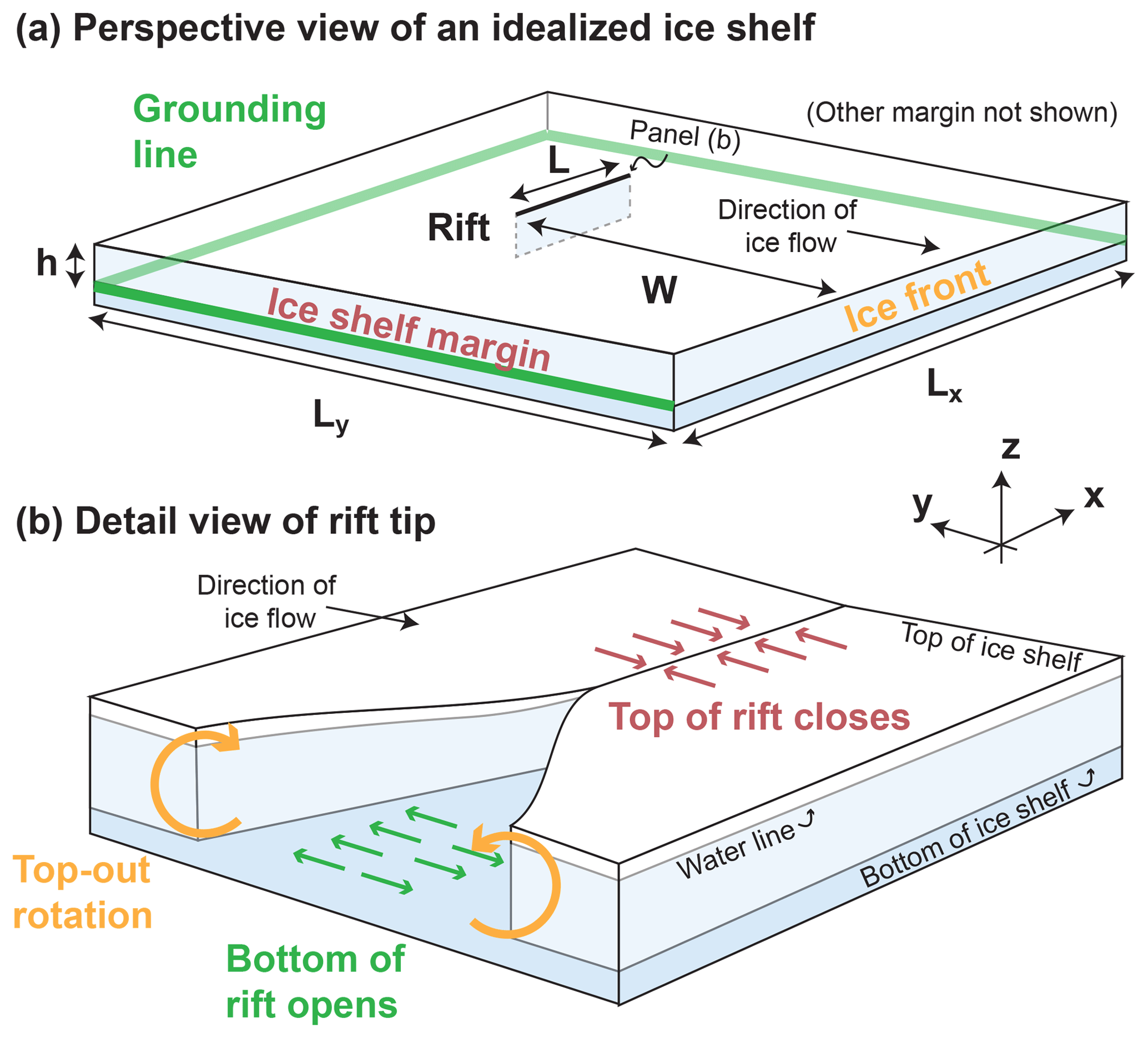
Figure 1(a) Ice shelf geometry used in this study. (b) View of rift tip showing partial contact of rift walls (drawn assuming distant margins).
I model rifts using linear elastic fracture mechanics (LEFM). Although a number of previous studies have examined ice shelf rifts using LEFM, no previous study appears to have considered three-dimensional effects. Hulbe et al. (2010) calculated two-dimensional mixed mode (in-plane opening and shearing) stress intensity factors and as a result were able to state a fracture condition as well as predict rift propagation paths. Other ice shelf LEFM studies have mostly focused on propagation paths (Plate et al., 2012; Levermann et al., 2012; Borstad et al., 2017) and near-tip deformation (Larour et al., 2004a, b).
A final point of background concerns the relationship between the forces that drive fracture and the background ice flow. In real ice shelves, the state of stress is constantly evolving due to the change in geometry brought about by ice flow. Previous studies have examined the relationship between ice flow and fracture in several ways. Hulbe et al. (2010) carried out viscous flow calculations to constrain the state of stress in their elastic calculations. They then tuned elastic moduli and boundary conditions in their elastic calculations to match the observed viscous stresses. Plate et al. (2012) parameterized a state of stress from a viscous flow model, but rather than tuning elastic moduli they instead chose to introduce fictitious equivalent body forces. Here, I consider the hypothesis that the forces that drive rift propagation are entirely described by the instantaneous ice shelf geometry and boundary conditions. This hypothesis requires three-dimensional calculations in order to directly calculate – rather than parameterize or approximate – the role of gravitational driving forces.
This paper is organized as follows. In Sect. 2, I describe three-dimensional elasticity calculations that are carried out using the finite element method and then post-processed to reveal fracture mechanical properties. I present three-dimensional results in Sect. 3. These results motivate a simplified two-dimensional treatment in Sect. 4, the results of which are given in Sect. 5. I conclude by discussing the relationship between rift propagation, the compressive arch, rift-filling melange, and ocean swell in Sect. 6.
2.1 Geometry
I consider the idealized ice shelf geometry shown in Fig. 1. The ice shelf is square in map view (the x–y plane). The z axis is defined so that the positive z axis points upwards and the bottom of the ice shelf is located at z=0. The ice shelf has horizontal dimensions km and thickness h=200 m. The ice shelf surface at y=0 faces the ocean and the surface at y=Ly faces the ice sheet. The surfaces at x=0 and x=Lx are referred to as the ice shelf margins. A single rift is located along the x axis at y=W. I treat two different general rift locations: marginal and central. These two rift locations are shown in Fig. 2. I hold the rift length fixed at L=2.5 km long for the marginal rift and L=5 km long for the central rift.
Geometrically, I model a rift as a rectangular hole in the ice shelf. Fractures in three dimensions have a fracture tip defined by a two-dimensional curve rather than a point. Although I refer to a rift tip for brevity, this term actually refers to a rift-tip curve. In the treatment presented here, the rift-tip curve is taken to be a vertical straight line. The rift is uniformly 10 m wide over most of its length. Simulations show low sensitivity to the choice of this width (for example, stress intensity factors, described later, show changes less than or on the order of 1 % change in response to changing the rift width to 15 m).
2.2 Linear elasticity
I consider the equations of linear, homogeneous, isotropic, static, three-dimensional elasticity (Malvern, 1969),
with total (Cauchy) stress tensor T′, ice density ρ, and gravitational acceleration g. Because I neglect any spatial variation in material parameters, my model does not include a firn layer. I account for an initial hydrostatic stress in a manner following Cathles (2015) wherein the equations of elasticity are solved for a perturbation stress tensor T defined as the total (Cauchy) stress tensor minus the initial overburden pressure,
with identity tensor I, overburden pressure
and ice sheet surface height H.
The perturbation stress tensor is necessary for the following physical reason. Without subtracting the initial overburden pressure, the ice shelf experiences an initial volumetric contraction with bulk modulus K. This volumetric contraction does not occur in real ice shelves because at timescales longer than the Maxwell time ice is well approximated as being incompressible (MacAyeal, 1989). Note that the perturbation stress tensor is not equal to the deviatoric stress tensor defined as , with isotropic pressure p. This difference is important because the perturbation stress tensor accurately captures permissible, elastic volumetric contraction, whereas the deviatoric stress tensor does not. The three-dimensional elasticity calculations in this study are carried out with respect to this perturbation stress tensor.
With respect to the perturbation stress tensor, the equations of motion are
The first of these equations describes momentum balance which is derived by combining Eqs. (2) and (3). Equation (5) describes the elastic constitutive relation (Hooke's law) with shear modulus μ=3.6 GPa and Poisson's ratio ν=0.3. Although isotropic elasticity only requires two elastic moduli, for convenience I use Young's modulus and the bulk modulus . Equation (6) defines the strain tensor ϵij. These equations use index notation with repeated indices implying summation, δij denoting the Kronecker delta function, and the indices i and j taking values and z.
2.2.1 Boundary conditions
The ice front, rift walls, and top and bottom ice shelf surfaces are loaded by a depth-varying normal stress that is equal to the water pressure below the waterline and equal to zero above the waterline. These boundaries have zero shear stress. The water pressure condition may be written as
Here pw is the depth-varying water pressure, n is the unit outward-pointing normal vector, is the ice shelf draft, and ρ and ρw are the ice and water densities.
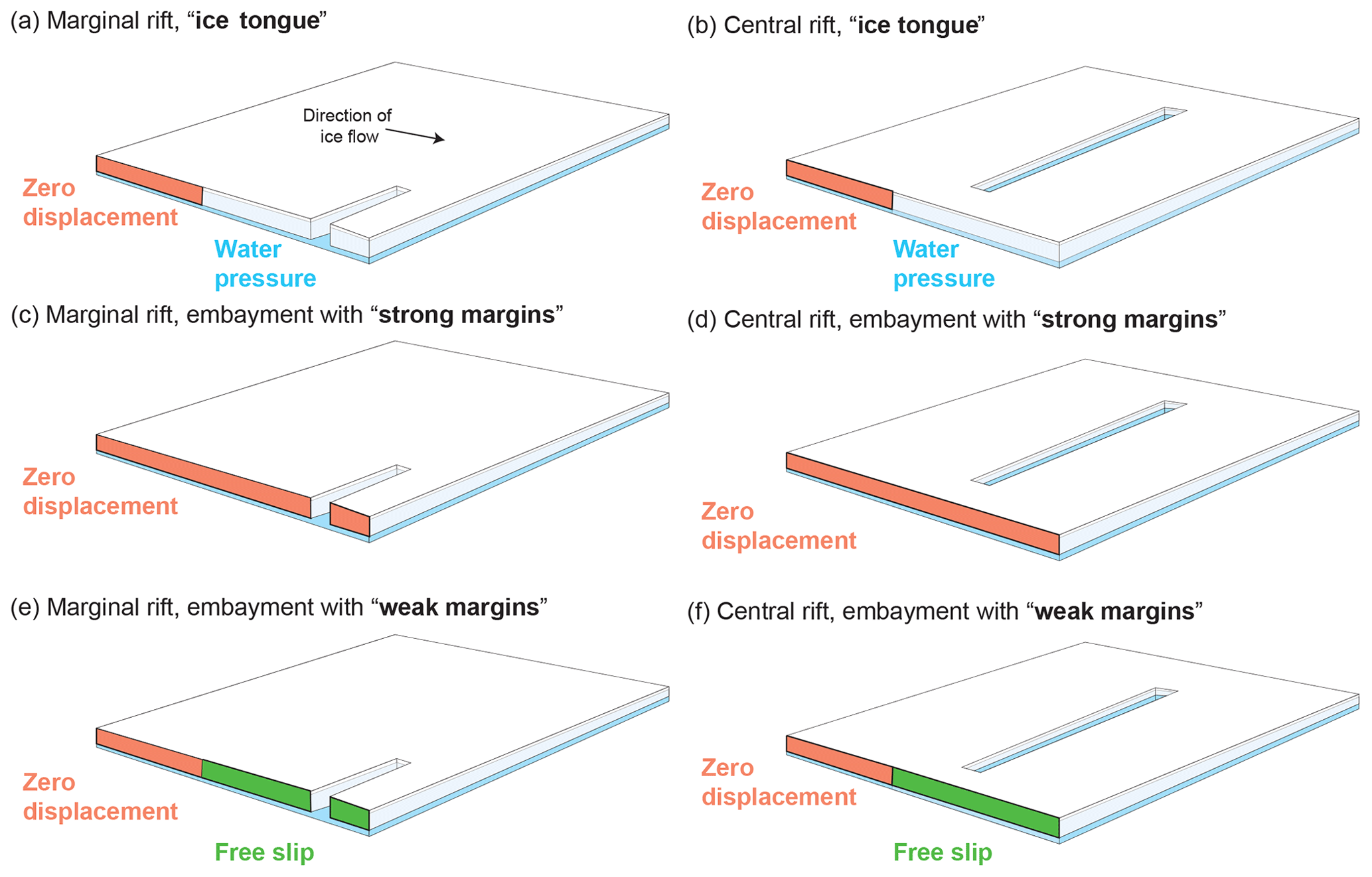
Figure 2The geometries and boundary conditions considered in this study: (a) and (b) ice tongue; (c) and (d) strong margins; and (e) and (f) zero displacement. Panels (a), (c), and (e) show marginal rifts and (b), (d), and (f) show central rifts. The figures are not drawn to scale.
The boundary conditions applied in the three-dimensional model are found by combining Eqs. (2), (7), and (8). This approach is consistent with previous treatments of crevasse propagation in glaciers (e.g., Van der Veen, 1998).
In all simulations, the surface of the ice shelf above the grounding line at y=Ly has a zero displacement boundary condition. Similarly, the ice shelf surface at the ice front at y=0 has a water pressure boundary condition (Eq. 8). In the margins, I examine three types of marginal boundary condition. These conditions are shown in Fig. 2; they are as follows.
-
Ice shelf with ice tongue. Margins have zero displacement between and y=Ly and have water pressure between y=0 and .
-
Ice shelf in an embayment with strong margins. Margins have zero displacement boundary condition.
-
Ice shelf in an embayment with weak margins. Margins have zero displacement between and y=Ly and have zero shear stress and zero normal displacement between y=0 and .
2.2.2 Numerical implementation
I solve Eqs. (4)–(6) using the finite element method. The ice shelf domain is discretized using a free (i.e., not regularly spaced) tetrahedral mesh. The maximum element size along the rift is h∕16. The element size then increases away from the rift to a maximum value of 3.5 km. The rift is geometrically formed as a rectangular prism with width Wrift=10 m and length L. The results presented here have minimal dependence on the choice of Wrift.
2.3 Linear elastic fracture
Fractures in elastic materials create displacement fields that are proportional to r1∕2 with distance to the crack tip r (Irwin, 1957). The scalar constant of proportionality involves the stress intensity factor. Specifically, in terms of the displacement components u, v, and w corresponding to displacements in the x, y, and z directions, the stress intensity factors are defined through the relations (Tada et al., 2000)
The quantities KI, KII, and KIII are the Mode I, Mode II, and Mode III stress intensity factors (SIFs). The sense of motion associated with each mode of fracture is shown in Fig. 3. Equations (9)–(11) represent the asymptotic value, accurate to the first order, of the displacement field near the rift tip on the plane of the fracture. The stress intensity factors bear a direct relationship to fracture propagation.
A basic tenet of fracture mechanics is that unstable crack growth occurs when the elastic strain energy available to drive fracture exceeds the energy required to create new fracture area (Griffith, 1921). The key insight of linear elastic fracture mechanics is that this energy condition can be related to the stress intensity factors (Irwin, 1957). The stress intensity factors may therefore be used as part of a fracture criterion. In this study, I examine mixed-mode fracture, and I therefore use the theory of Erdogan and Sih (1963) that calculates the single optimally oriented stress intensity factor from the three different stress intensity modes. This optimally oriented stress intensity factor is the Mode I stress intensity factor along a plane oriented to minimize KII and KIII (Erdogan and Sih, 1963; Hulbe et al., 2010). Under the assumption (verified later) that KIII does not substantially contribute to the direction of propagation of the rift-tip line, the Mode I stress intensity factor along the optimal angle of propagation θ can be written as
In this expression, the angle of propagation θ is given by
In the adopted sign convention, negative angles indicate the direction pointing away from the ice front, and straight-ahead propagation occurs when θ=0. Note that care must be taken in selecting the correct quadrant for the tan −1 function.
The fracture propagation criteria may then be stated as
where the value KIc=100 kPa m1∕2 is the Mode I fracture toughness of ice (Rist et al., 2002). I refer to rifts that satisfy Eq. (14) as being unstable because they are expected to undergo some amount of propagation. Note that this does not necessarily mean that the rift will propagate in a way that will lead to a calving event. Propagation may stop, for example, before calving occurs. Rifts that do not satisfy Eq. (14) will be referred to as stable; such rifts are expected to close.
2.3.1 Partial contact of rift walls
The partial contact of rift walls is a nonlinear phenomenon because it involves solving for the shape of the contacting region and therefore changing the region over which different boundary conditions are applied (Johnson and Johnson, 1987). Here, I treat a linear formulation of this problem wherein the Mode I stress intensity factor KI can take on positive or negative values. This situation is discussed in detail by Tada et al. (2000). For fractures with zero initial width, a negative KI implies unphysical material overlap. I avoid this situation in my numerical simulations by giving the rift an initial nonzero opening as described in Sect. 2.1. This is consistent with the idea that rifts in ice shelves are probably not held open entirely by elastic stresses because they have deformed through creeping flow. Other studies have shown that accounting for contact nonlinearity results in minimal differences from the linear problem for long fractures with L≫λ (Liu et al., 1999), where λ is the ice shelf flexural wavelength (discussed later; see Eq. 22). Given that many rifts do reach lengths L≫λ (Walker et al., 2013, 2015), the linear approximation may well prove adequate for many cases of glaciological interest.
2.3.2 Stress intensity factor calculations
The stress intensity factors are calculated by solving Eqs. (9)–(11) numerically at an arbitrary distance r from the crack tip. This evaluation method, essentially a post-processing step, is sometimes called the displacement correlation method (Zehnder, 2012) and has previously been used in glacier studies by Jimenez and Duddu (2018). I evaluate Eqs. (9)–(11) at a distance r from the crack tip that is at least several times the grid spacing in order to achieve grid-size independence. In three dimensions, stress intensity factors are calculated at various heights through the ice shelf thickness, with the resulting calculations plotted in Fig. 3.
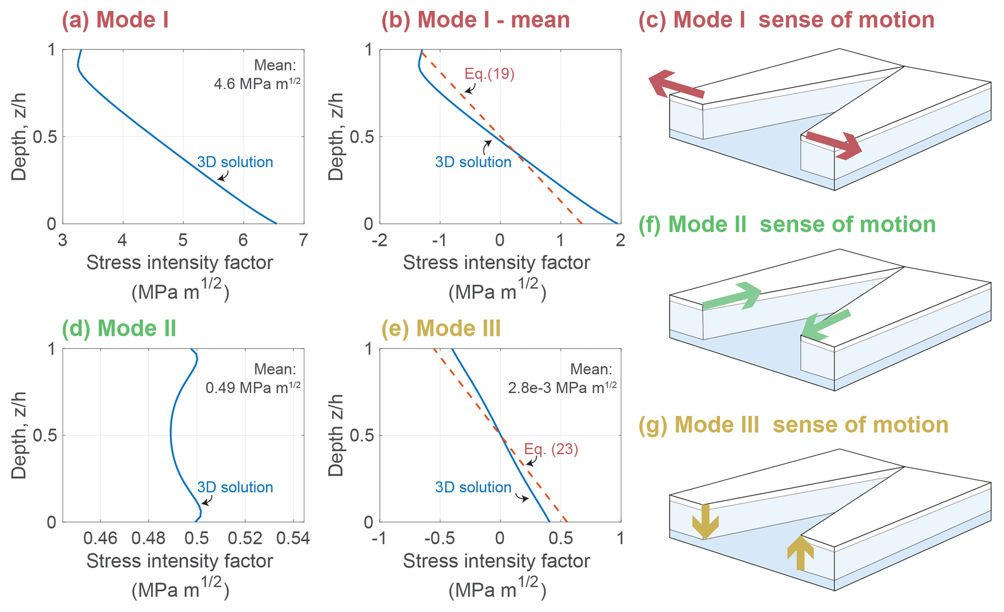
Figure 3Typical three-dimensional stress intensity factors (SIFs) as a function of depth z in the ice shelf. The particular SIFs are for a marginal rift in an ice tongue (Fig. 2a). (a) Mode I stress intensity factor (SIF), (b) Mode I SIF with depth-mean removed, (c) Mode I sense of motion, (d) Mode II SIF, (e) Mode III SIF, (f) Mode II sense of motion, and (g) Mode III sense of motion. Red dashed lines show the analytical parameterizations in the 2D model (Sect. 4).
Figure 3 shows a typical result of the finite element calculations. This figure shows that the Mode I and Mode III stress intensity factors are nearly linear with depth (i.e., Fig. 3a, b, and e), while the Mode II stress intensity factor is nearly uniform with depth (i.e., Fig. 3d). Empirically, the structure of the three-dimensional stress intensity factors can be described as
I refer to the different terms on the right-hand side of Eqs. (15)–(17) as the stress intensity factor components. In these components, the superscripts “b” and “m” stand for bending and membrane, respectively. I recall that, in general, each of the stress intensity factor components is expected to depend on the ice shelf geometry, (e.g., Lx, Ly, h, L, and W).
I estimate the individual components of the stress intensity factors from the three-dimensional solutions (Fig. 3). In these solutions, the depth-varying part of the stress intensity factors corresponds to contributions from bending motion. Bending only affects the Mode I and Mode II stress intensity factors. The depth-independent part of the stress intensity factors corresponds to contributions from in-plane or membrane motion. Membrane motion affects only the Mode I and Mode II stress intensity factors. This observed structure motivates the following parameterized, two-dimensional treatment.
I now examine a parameterized two-dimensional model with the goal of approximating Eqs. (15)–(17). The membrane terms and are calculated numerically by solving the equations of plane strain elasticity in two horizontal spatial dimensions x and y. The governing equations for the two-dimensional calculations are found by taking in Eqs. (4)–(6). The two-dimensional finite element calculations are similar to the three-dimensional ones, with tetrahedral elements being replaced by triangular ones and a minimum mesh size Wrift∕10. Boundary conditions are chosen, as in the three-dimensional calculations, to be either freely slipping, to have zero displacement, or to have an applied traction that represents an ice front. The latter is given by the classical ice front membrane stress solution of Weertman (1957),
Note that this boundary condition is simply the depth-integrated water pressure minus overburden pressure as given in Eqs. (7)–(8).
Bending terms and , in contrast, are parameterized based on the following analytical treatment. I find that the bending contribution to the opening mode is well fit by the stress intensity factor solution (Sih, 2012),
with bending stress (Reeh, 1968)
The bending stress σb is the value of the rift-normal stress at the top of the ice shelf; it is also the maximum value of the rift-normal stress. The bending stress can be expressed as a bending moment,
Typical values of give ϕ=0.08. In addition, Eq. (19) makes use of the flexural gravity parameter,
with flexural rigidity . Hence, flexure results in a stabilizing contribution to the Mode I stress intensity factor that grows with ice thickness according to . The function f(ν) is discussed below. Notably, the bending stress intensity factors asymptotically vary with instead of the typical .
There is some discrepancy in the literature concerning the precise values of the function f(ν). Sih (2012) cites Folias (1970), who both note that f is of the order of unity but do not give its exact form. Ang et al. (1963) appear to have first given the dependence of f on ν although Sih and Setzer (1964) found a mistake in this work. Meanwhile, Bažant (1992) gives a different value of f. It appears, however, that Bažant (1992) did not correctly account for the rift-wall boundary condition. Given this uncertainty and the additional detail involved in the three-dimensional problem beyond the assumptions made by the above authors, I instead simply choose to calculate the value of f(ν) from the three-dimensional calculations. From these calculations, I find a value . Of the above references, this value is most similar to the value calculated from the equation given by Sih and Setzer (1964), .
Bending also creates a Mode III stress intensity factor. Assuming that this bending can also be described within Euler beam theory, the Mode III and Mode I stress intensity factors are related by a factor,
Thus , which is a larger exponent than for . This solution was derived by assuming, consistent with Eqs. (9)–(11), that the ratio of stress intensity factors is proportional to the ratio of the stresses. This stress ratio is then calculated using the solution to the floating beam equation (Hetényi, 1971), . The analytical solution of Eq. (23) is compared to the finite element solution in Fig. 3e (red dashed lines).
5.1 Comparison between 2D and 3D
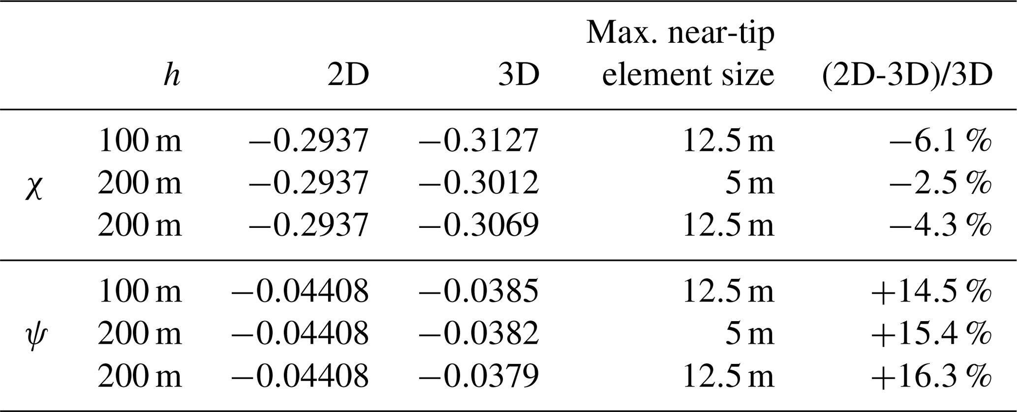
I find good agreement between two-dimensional calculations and the depth-averaged values from three-dimensional calculations. Table 1 presents these results using the geometrical factors and , where σm is the depth-integrated boundary condition given in Eq. (18). Note that suggests that χ and ψ do not depend on L (Tada et al., 2000). The agreement is better for χ than for ψ, with differences on the order of several percent. This table also shows the effect of varying the maximum near-tip element length. The values in this table are calculated for a central rift in an embayment with strong margins (i.e., as shown in Fig. 2d).
The analytical solution is not expected to perfectly match the finite element solution because the latter accounts for the full floatation condition (Eq. 7), whereas the bending model (Eq. 19) neglects higher-order moments through Eq. (21). I further verify that the simplified model captures the behavior of the three-dimensional simulations by calculating stress intensity factors over a range of ice shelf thickness between 25 m and 1600 m. I find that in the three-dimensional calculations whereas analytically. Similarly, in the three-dimensional calculations whereas analytically. As can be seen in Fig. 3, the differences are more pronounced for . I attribute the differences between analysis and calculation to the neglect of higher-order moments and stress terms (i.e., the use of Euler beam theory).
5.2 Marginal and central rifts
I use the two-dimensional approach described in Sect. 4 to examine the effect of rift position on rift stability. I consider all combinations of boundary conditions and rift locations shown in Fig. 2 while additionally varying the streamwise position of the rift W.
Stress intensity factors for marginal rifts are plotted in Fig. 4. Consistent with the shearing stresses experienced in the ice shelf margins, the Mode I and Mode II stress intensity factors are of similar magnitude (Fig. 4a and b, respectively). In all marginal rift simulations, rifts propagate away from the ice front (Fig. 4c). Marginal rifts are unstable over the greatest range of locations in the ice tongue and weak margin geometries (Fig. 4d). In both cases, rifts are unstable at positions . Marginal rifts in ice shelves with strong margins, in contrast, are stable near the grounding line and they become unstable at a distance from the ice front.
Stress intensity factors for central rifts are plotted in Fig. 5. In contrast to marginal rifts, central rifts have (Fig. 5a and b). Unlike marginal rifts, propagation angles are smaller, indicating nearly straight-ahead propagation (Fig. 5c). Central rifts in all positions are found to have negative optimally oriented stress intensity factors indicative of stability (Fig. 5d).

Figure 4Stress intensity factors for marginal rifts may reflect either stability or instability depending on the position of the rift. Three pieces of information, the (a) Mode I SIF, (b) Mode II SIF, and (c) propagation angle, are combined using Eq. (12) to calculate (d) the optimally oriented SIF.
I have presented a three-dimensional LEFM analysis of ice shelf rift propagation. While this model has many potential applications, I have focused on the relationship between marginal strength and rift stability. In that regard, the main result of this analysis is that rifts originating in the margins of ice shelves become unstable if the ice shelf margin looses shear strength. This transition between a strong margin and a weak margin can be seen, for example, by comparing the red and yellow curves in Fig. 4d. Although this result is justified by the calculations presented in this paper, it is worth emphasizing several assumptions.
I have assumed that margins have either zero displacement or zero shear stress. In reality, margins likely experienced reduced but nonzero shear stress. I have also considered only two rift locations (marginal or central), only one ice shelf geometry (square), and only one rift geometry (a single rift, perpendicular to flow, and without curvature). I treat the entire ice column as having uniform material properties and therefore describe neither a firn layer nor its relation to partial contact of rift walls. Additional observed rift-wall processes such as brine infiltration, surface accumulation, and variable uplift could also be investigated (Scambos et al., 2009, 2013; Walker and Gardner, 2019). Each of these assumptions deserves further examination. Despite these limitations, ice shelves and ice shelf rifts oftentimes approximately conform to the assumptions described in this study. I do therefore expect that the results presented here provide a useful basis for understanding rift propagation.

6.1 The compressive arch
All boundary conditions considered here give rise to a compressive arch, defined as the region where an ice shelf transitions from uniaxial to biaxial extension (Fig. 6). Doake et al. (1998) proposed the hypothesis that “once a retreating ice front breaks through the critical `compressive arch' then retreat is irreversible”. Although the results presented here broadly confirm a connection between the compressive arch and rift propagation, there are important caveats. The foremost exception to the compressive arch hypothesis is that central rifts are found to always be stable, regardless of their position inside or outside of the compressive arch. Additionally, for the strong margin boundary condition the onset of instability occurs somewhat upstream from the maximum extent of the compressive arch. This is shown in Fig. 6a, where the compressive arch is plotted as a black dashed line and marginal stability boundaries are plotted with yellow dashed lines. For the weak margins and ice tongue boundary conditions the agreement is closer; however, there is also a region of stability that occurs closer to the ice front (Fig. 6b and c). Perhaps most importantly, the results presented here suggest a slightly different order of causality than that proposed by Doake et al. (1998). In the hypothesis of Doake et al. (1998), the compressive arch is a boundary that rifts may or may not propagate through. The present analysis instead suggests that a rift “propagating across the compressive arch”, actually involves simultaneous changes in ice geometry, migration of the compressive arch, and rift propagation. Under the assumptions of my analysis, calving of icebergs within the compressive arch is only reversible insofar as marginal weakening is irreversible.
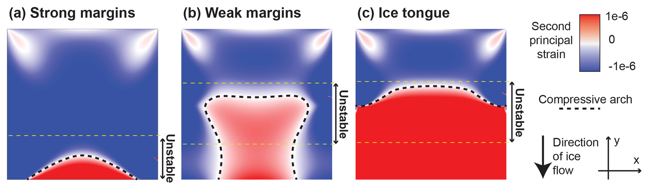
Figure 6The ice shelf compressive arch (thick black dashed line) is plotted for three boundary conditions: (a) strong margins, (b) weak margins, and (c) ice tongue (see Fig. 2). The figure also shows the boundaries of regions of instability for marginal rifts (thin yellow dashed lines). These figures were calculated in two horizontal spatial dimensions as described in Sect. 4.
6.2 Melange as a rift proppant
Olinger et al. (2019) observed a lack of rift-tip seismicity at a central rift in the Ross Ice Shelf. This observation is qualitatively consistent with the negative I have calculated for centrally located rifts. A negative stress intensity factor indicates a rift that will tend to close. It seems likely that these rifts therefore owe their continued existence to rift-filling melange that acts as a type of proppant by holding the rift open. Melange therefore has a dual nature. MacAyeal et al. (1998) and Rignot and MacAyeal (1998) showed that melange maintains shear stresses and therefore resists viscous flow. In this sense, melange is stabilizing. Yet in the sense that melange may sometimes enable the existence of rifts that would otherwise close, melange is destabilizing.
6.3 Wave-induced fracture
Lipovsky (2018) used passive seismic data to calculate the elastic ice shelf stresses due to ocean swell acting on the Ross Ice Shelf. This study concluded that some un-modeled process must have been operating in order to explain the lack of any observed ice shelf rift propagation during the observation period. Specifically, Lipovsky (2018) calculated a maximum wave-induced Mode I stress intensity factor KI≈2 MPa m1∕2 for a site near the Nascent Iceberg Rift. Using the results presented here for a central rift, we calculate that for a near-front central rift with , the Mode I stress intensity without wave stress would be MPa m1∕2. The resulting total Mode I stress intensity factor of MPa m1∕2 being negative is consistent with the observation that ocean swell did not trigger rift propagation during the observation period described by Lipovsky (2018).
I have modeled an ice shelf as a three-dimensional buoyantly floating elastic plate. I then show how these three-dimensional results may be captured in simplified two-dimensional calculations. Using the two-dimensional theory, I show that ice shelf rifts become unstable in the presence of marginal weakening or upon exiting an embayment. These results are a step towards modeling marine ice sheet evolution with a physics-based relationship between ice flow and an ice extent set by rift propagation.
The analysis code used in the text is available on the author's GitHub repository https://doi.org/10.5281/zenodo.3774467 (Lipovsky, 2020).
The author declares that there is no conflict of interest.
This project began with a discussion with Colin Meyer at the Cambridge symposium of the International Glaciological Society in 2015. Jim Rice and Eric Dunham read earlier versions of this manuscript and gave helpful comments. Several discussions with Brent Minchew, Jan De Rydt, and Hilmar Gudmundsson also provided interesting feedback along the way. On a visit to C.U. Boulder organized by Jed Brown, David Marshall was critical of some early results; this feedback was helpful.
This paper was edited by Olivier Gagliardini and reviewed by three anonymous referees.
Ang, D., Folias, E., and Williams, M.: The bending stress in a cracked plate on an elastic foundation', J. Appl. Mechan., 30, 245–251, 1963. a
Arndt, J. E., Larter, R. D., Friedl, P., Gohl, K., Höppner, K., and the Science Team of Expedition PS104: Bathymetric controls on calving processes at Pine Island Glacier, The Cryosphere, 12, 2039–2050, https://doi.org/10.5194/tc-12-2039-2018, 2018. a
Banwell, A. F., MacAyeal, D. R., and Sergienko, O. V.: Breakup of the Larsen B Ice Shelf triggered by chain reaction drainage of supraglacial lakes, Geophys. Res. Lett., 40, 5872–5876, 2013. a, b
Bažant, Z. P.: Large-scale thermal bending fracture of sea ice plates, J. Geophys. Res.-Oceans, 97, 17739–17751, 1992. a, b
Borstad, C., McGrath, D., and Pope, A.: Fracture propagation and stability of ice shelves governed by ice shelf heterogeneity, Geophys. Res. Lett., 44, 4186–4194, 2017. a
Budd, W.: The dynamics of the Amery ice shelf, J. Glaciol., 6, 335–358, 1966. a
Cathles, L. M.: Viscosity of the Earth's Mantle, vol. 1362, Princeton University Press, 2015. a
De Rydt, J., Gudmundsson, G. H., Nagler, T., Wuite, J., and King, E. C.: Recent rift formation and impact on the structural integrity of the Brunt Ice Shelf, East Antarctica, The Cryosphere, 12, 505–520, https://doi.org/10.5194/tc-12-505-2018, 2018. a
Doake, C., Corr, H., Rott, H., Skvarca, P., and Young, N.: Breakup and conditions for stability of the northern Larsen Ice Shelf, Antarctica, Nature, 391, 778–780, 1998. a, b, c, d
Erdogan, F. and Sih, G.: On the crack extension in plates under plane loading and transverse shear, J. Basic Eng., 85, 519–525, 1963. a, b
Folias, E.: On a plate supported by an elastic foundation and containing a finite crack, Int. J. Fract. Mechan., 6, 257–263, 1970. a
Glasser, N. and Scambos, T. A.: A structural glaciological analysis of the 2002 Larsen B ice-shelf collapse, J. Glaciol., 54, 3–16, 2008. a
Goldberg, D., Holland, D., and Schoof, C.: Grounding line movement and ice shelf buttressing in marine ice sheets, J. Geophys. Res.-Earth Surf., 114, F04026, https://doi.org/10.1029/2008JF001227, 2009. a
Graham, A. G., Dutrieux, P., Vaughan, D. G., Nitsche, F. O., Gyllencreutz, R., Greenwood, S. L., Larter, R. D., and Jenkins, A.: Seabed corrugations beneath an Antarctic ice shelf revealed by autonomous underwater vehicle survey: origin and implications for the history of Pine Island Glacier, J. Geophys. Res.-Earth Surf., 118, 1356–1366, 2013. a
Griffith, A. A.: The phenomena of rupture and flow in solids, Philos. Trans. Roy. Soc. London, 221, 163–198, 1921. a
Gudmundsson, G. H.: Ice-shelf buttressing and the stability of marine ice sheets, The Cryosphere, 7, 647–655, https://doi.org/10.5194/tc-7-647-2013, 2013. a
Hetényi, M.: Beams on elastic foundation: theory with applications in the fields of civil and mechanical engineering, BOOK, University of Michigan, 1971. a
Hughes, T.: West Antarctic ice streams, Rev. Geophys., 15, 1–46, 1977. a
Hulbe, C. L., LeDoux, C., and Cruikshank, K.: Propagation of long fractures in the Ronne Ice Shelf, Antarctica, investigated using a numerical model of fracture propagation, J. Glaciol., 56, 459–472, 2010. a, b, c
Irwin, G. R.: Analysis of stresses and strains near the end of a crack traversing a plate, J. Appl. Mechan., 24, 361–364, 1957. a, b
Jimenez, S. and Duddu, R.: On the evaluation of the stress intensity factor in calving models using linear elastic fracture mechanics, J. Glaciol., 64, 759–770, 2018. a
Johnson, K. L. and Johnson, K. L.: Contact mechanics, Cambridge university press, 1987. a
Joughin, I., Howat, I. M., Fahnestock, M., Smith, B., Krabill, W., Alley, R. B., Stern, H., and Truffer, M.: Continued evolution of Jakobshavn Isbrae following its rapid speedup, J. Geophys. Res.-Earth Surf., 113, F04006, https://doi.org/10.1029/2008JF001023, 2008. a
Khazendar, A., Rignot, E., and Larour, E.: Larsen B Ice Shelf rheology preceding its disintegration inferred by a control method, Geophys. Res. Lett., 34, L19503, https://doi.org/10.1029/2007GL030980, 2007. a
Larour, E., Rignot, E., and Aubry, D.: Modelling of rift propagation on Ronne Ice Shelf, Antarctica, and sensitivity to climate change, Geophys. Res. Lett., 31, L16404, https://doi.org/10.1029/2004GL020077, 2004a. a
Larour, E., Rignot, E., and Aubry, D.: Processes involved in the propagation of rifts near Hemmen ice rise, Ronne ice shelf, Antarctica, J. Glaciol., 50, 329–341, 2004b. a
Leeson, A., Forster, E., Rice, A., Gourmelen, N., and Van Wessem, J.: Evolution of supraglacial lakes on the Larsen B ice shelf in the decades before it collapsed, Geophys. Res. Lett., 47, e2019GL085591. https://doi.org/10.1029/2019GL085591, 2020. a
Levermann, A., Albrecht, T., Winkelmann, R., Martin, M. A., Haseloff, M., and Joughin, I.: Kinematic first-order calving law implies potential for abrupt ice-shelf retreat, The Cryosphere, 6, 273–286, https://doi.org/10.5194/tc-6-273-2012, 2012. a
Lipovsky, B. P.: Ice Shelf Rift Propagation and the Mechanics of Wave-Induced Fracture, J. Geophys. Res.-Oceans, 123, 4014–4033, https://doi.org/10.1029/2017JC013664, 2018. a, b, c
Lipovsky, B.: bradlipovsky/Lipovsky2020_Ice_Shelf_Rifts: Stress intensity factor solutions for rifts in a square ice shelf (Version v1.0). Zenodo. https://doi.org/10.5281/zenodo.3774467, 2020. a
Liu, R., Wang, C., and Bathgate, R.: Crack closure in spherical shells, In. J. Fract., 99, 307–323, 1999. a
MacAyeal, D. R.: Large-scale ice flow over a viscous basal sediment: Theory and application to ice stream B, Antarctica, J. Geophys. Res.-Solid Earth, 94, 4071–4087, 1989. a, b
MacAyeal, D. R., Rignot, E., and Hulbe, C. L.: Ice-shelf dynamics near the front of the Filchner-Ronne Ice Shelf, Antarctica, revealed by SAR interferometry: model/interferogram comparison, J. Glaciol., 44, 419–428, 1998. a
MacGregor, J. A., Catania, G. A., Markowski, M. S., and Andrews, A. G.: Widespread rifting and retreat of ice-shelf margins in the eastern Amundsen Sea Embayment between 1972 and 2011, J. Glaciol., 58, 458–466, 2012. a, b
Malvern, L. E.: Introduction to the Mechanics of a Continuous Medium, Monograph, Prentice-Hall, Inc. in Englewood Cliffs, NJ, 1969. a
Marcott, S. A., Clark, P. U., Padman, L., Klinkhammer, G. P., Springer, S. R., Liu, Z., Otto-Bliesner, B. L., Carlson, A. E., Ungerer, A., Padman, J., and He, F.,: Ice-shelf collapse from subsurface warming as a trigger for Heinrich events, P. Natl. Acad. Sci. USA, 108, 13415–13419, 2011. a
Naish, T., Powell, R., Levy, R., Wilson, G., Scherer, R., Talarico, F., Krissek, L., Niessen, F., Pompilio, M., Wilson, T., and Carter, L.: Obliquity-paced Pliocene West Antarctic ice sheet oscillations, Nature, 458, 322, 2009. a
Olinger, S., Lipovsky, B., Wiens, D., Aster, R., Bromirski, P., Chen, Z., Gerstoft, P., Nyblade, A., and Stephen, R.: Tidal and Thermal Stresses Drive Seismicity along a Major Ross Ice Shelf Rift, Geophys. Res. Lett., 46, 6644–6652, https://doi.org/10.1029/2019GL082842, 2019. a
Pattyn, F., Ritz, C., Hanna, E., Asay-Davis, X., DeConto, R., Durand, G., Favier, L., Fettweis, X., Goelzer, H., Golledge, N. R., and Munneke, P. K.: The Greenland and Antarctic ice sheets under 1.5 ∘C global warming, Nat. Clim. Change, 8, 1053–1061, https://doi.org/10.1038/s41558-018-0305-8, 2018. a
Plate, C., Gross, D., Humbert, A., and Müller, R.: Analysis of Calving Events in Antarctic Ice Shelves Using Configurational Forces, P. Appl. Mathe. Mechan., 12, 155–156, 2012. a, b
Reeh, N.: On the calving of ice from floating glaciers and ice shelves, J. Glaciol., 7, 215–232, 1968. a, b
Rignot, E. and MacAyeal, D. R.: Ice-shelf dynamics near the front of the Filchner Ronne Ice Shelf, Antarctica, revealed by SAR interferometry, J. Glaciol., 44, 405–418, 1998. a
Rignot, E., Casassa, G., Gogineni, P., Krabill, W., Rivera, A., and Thomas, R.: Accelerated ice discharge from the Antarctic Peninsula following the collapse of Larsen B ice shelf, Geophys. Res. Lett., 31, L18401, https://doi.org/10.1029/2004GL020697, 2004. a
Rist, M., Sammonds, P., Oerter, H., and Doake, C.: Fracture of Antarctic shelf ice, J. Geophys. Res.-Solid Earth, 107, 2002, https://doi.org/10.1029/2000JB000058, 2002. a
Sanderson, T.: Equilibrium profile of ice shelves, J. Glaciol., 22, 435–460, 1979. a, b
Scambos, T., Fricker, H. A., Liu, C.-C., Bohlander, J., Fastook, J., Sargent, A., Massom, R., and Wu, A.-M.: Ice shelf disintegration by plate bending and hydro-fracture: Satellite observations and model results of the 2008 Wilkins Ice Shelf break-ups, Earth Planet. Sci. Lett., 280, 51–60, 2009. a
Scambos, T., Ross, R., Haran, T., Bauer, R., Ainley, D., Seo, K.-W., De Keyser, M., Behar, A., and MacAyeal, D.: A camera and multisensor automated station design for polar physical and biological systems monitoring: AMIGOS, J. Glaciol., 59, 303–314, 2013. a
Scambos, T. A., Hulbe, C., Fahnestock, M., and Bohlander, J.: The link between climate warming and break-up of ice shelves in the Antarctic Peninsula, J. Glaciol., 46, 516–530, 2000. a
Scambos, T. A., Bohlander, J., Shuman, C. U., and Skvarca, P.: Glacier acceleration and thinning after ice shelf collapse in the Larsen B embayment, Antarctica, Geophys. Res. Lett., 31, L18402, https://doi.org/10.1029/2004GL020670, 2004. a
Seroussi, H., Nowicki, S., Payne, A. J., Goelzer, H., Lipscomb, W. H., Abe Ouchi, A., Agosta, C., Albrecht, T., Asay-Davis, X., Barthel, A., Calov, R., Cullather, R., Dumas, C., Gladstone, R., Golledge, N., Gregory, J. M., Greve, R., Hatterman, T., Hoffman, M. J., Humbert, A., Huybrechts, P., Jourdain, N. C., Kleiner, T., Larour, E., Leguy, G. R., Lowry, D. P., Little, C. M., Morlighem, M., Pattyn, F., Pelle, T., Price, S. F., Quiquet, A., Reese, R., Schlegel, N.-J., Shepherd, A., Simon, E., Smith, R. S., Straneo, F., Sun, S., Trusel, L. D., Van Breedam, J., van de Wal, R. S. W., Winkelmann, R., Zhao, C., Zhang, T., and Zwinger, T.: ISMIP6 Antarctica: a multi-model ensemble of the Antarctic ice sheet evolution over the 21st century, The Cryosphere Discuss., https://doi.org/10.5194/tc-2019-324, in review, 2020. a
Sih, G. and Setzer, D.: Discussion: The Bending Stress in a Cracked Plate on an Elastic Foundation (Ang, DD, Folias, ES, and Williams, ML, 1963, ASME J. Appl. Mech., 30, pp. 245–251), J. Appl. Mechan., 31, 365–366, 1964. a, b
Sih, G. C.: Plates and shells with cracks: a collection of stress intensity factor solutions for cracks in plates and shells, vol. 3, Springer Science & Business Media, 2012. a, b
Tada, H., Paris, P. C., and Irwin, G. R.: The stress analysis of cracks, Handbook, Del Research Corporation, 2000. a, b, c, d
Thomas, R. H. and Bentley, C. R.: A model for Holocene retreat of the West Antarctic ice sheet, Quaternary Res., 10, 150–170, 1978. a
Van der Veen, C.: Fracture mechanics approach to penetration of surface crevasses on glaciers, Cold Reg. Sci. Technol., 27, 31–47, 1998. a
Vieli, A., Payne, A. J., Du, Z., and Shepherd, A.: Numerical modelling and data assimilation of the Larsen B ice shelf, Antarctic Peninsula, Philos. Trans. Roy. Soc. A, 364, 1815–1839, 2006. a
Walker, C. and Gardner, A.: Evolution of ice shelf rifts: Implications for formation mechanics and morphological controls, Earth Planet. Sci. Lett., 526, 115764, https://doi.org/10.1016/j.epsl.2019.115764, 2019. a
Walker, C., Bassis, J., Fricker, H., and Czerwinski, R.: Structural and environmental controls on Antarctic ice shelf rift propagation inferred from satellite monitoring, J. Geophys. Res.-Earth Surf., 118, 2354–2364, 2013. a
Walker, C. C., Bassis, J. N., Fricker, H. A., and Czerwinski, R. J.: Observations of interannual and spatial variability in rift propagation in the Amery Ice Shelf, Antarctica, 2002–14, J. Glaciol., 61, 243–252, 2015. a
Weertman, J.: Deformation of floating ice shelves, J. Glaciol., 3, 38–42, 1957. a, b
Yokoyama, Y., Anderson, J. B., Yamane, M., Simkins, L. M., Miyairi, Y., Yamazaki, T., Koizumi, M., Suga, H., Kusahara, K., Prothro, L., and Hasumi, H.: Widespread collapse of the Ross Ice Shelf during the late Holocene, P. Natl. Acad. Sci. USA, 113, 2354–2359, 2016. a
Zehnder, A. T.: Fracture mechanics, Springer, London, Dordrecht, Heidelberg, New York, 2012. a