the Creative Commons Attribution 4.0 License.
the Creative Commons Attribution 4.0 License.
 | 28 Jul 2021
Acoustic velocity measurements for detecting the crystal orientation fabrics of a temperate ice core
Sebastian Hellmann
Melchior Grab
Johanna Kerch
Henning Löwe
Andreas Bauder
Ilka Weikusat
Hansruedi Maurer
The crystal orientation fabric (COF) in ice cores provides detailed information, such as grain size and distribution and the orientation of the crystals in relation to the large-scale glacier flow. These data are relevant for a profound understanding of the dynamics and deformation history of glaciers and ice sheets. The intrinsic, mechanical anisotropy of the ice crystals causes an anisotropy of the polycrystalline ice of glaciers and affects the velocity of acoustic waves propagating through the ice. Here, we employ such acoustic waves to obtain the seismic anisotropy of ice core samples and compare the results with calculated acoustic velocities derived from COF analyses. These samples originate from an ice core from Rhonegletscher (Rhone Glacier), a temperate glacier in the Swiss Alps. Point-contact transducers transmit ultrasonic P waves with a dominant frequency of 1 MHz into the ice core samples and measure variations in the travel times of these waves for a set of azimuthal angles. In addition, the elasticity tensor is obtained from laboratory-measured COF, and we calculate the associated seismic velocities. We compare these COF-derived velocity profiles with the measured ultrasonic profiles. Especially in the presence of large ice grains, these two methods show significantly different velocities since the ultrasonic measurements examine a limited volume of the ice core, whereas the COF-derived velocities are integrated over larger parts of the core. This discrepancy between the ultrasonic and COF-derived profiles decreases with an increasing number of grains that are available within the sampling volume, and both methods provide consistent results in the presence of a similar amount of grains. We also explore the limitations of ultrasonic measurements and provide suggestions for improving their results. These ultrasonic measurements could be employed continuously along the ice cores. They are suitable to support the COF analyses by bridging the gaps between discrete measurements since these ultrasonic measurements can be acquired within minutes and do not require an extensive preparation of ice samples when using point-contact transducers.
- Article
(7953 KB) - Full-text XML
- BibTeX
- EndNote


Improved glacier flow models require a profound knowledge on sub- and englacial processes and the properties governing these processes. The data for studying englacial processes are usually derived either from borehole measurements or from ice core analyses. These ice core analyses provide useful physical properties, such as elastic parameters, density, electric conductivity, and permittivity (e.g. Freitag et al., 2004; Wilhelms, 2005). Most of these properties are anisotropic in ice cores because the physical properties of a single ice crystal vary along its principal axes, and the crystals usually exhibit preferential orientations under deformation. Furthermore, ice cores provide geometric details on the ice microstructure, such as grain size and shape, and information on crystal orientation. The derived crystal orientation fabric (COF) describes the orientation of the ice grains' c axes, which are the symmetry axes of the individual ice monocrystals in the polycrystalline material. The COF is governed by the stress field and the ice deformation and thus preserves the ice flow history of a glacier or ice sheet (Budd, 1972; Azuma and Higashi, 1984; Alley, 1988). It is also an indicator for the internal ice structure at the ice core location, which allows for a classification of the ice as “soft” or “hard” depending on the direction of the strain rates relative to the COF (e.g. Budd and Jacka, 1989; Faria et al., 2014). Such information is crucial for improving glacier flow models that consider anisotropy effects (Alley, 1992; Azuma, 1994). For example, information on the anisotropic ice flow dynamics of a glacier has successfully been incorporated in ice flow models by Gillet-Chaulet et al. (2005), Placidi et al. (2010), and Graham et al. (2018).
For the analysis of the COF, thin sections of ice (≈ 350 µm thick) are manually prepared from ice core samples and finally measured with an automated fabric analyser (e.g. Wilson et al., 2003; Peternell et al., 2009). This processing workflow is state of the art, but it is labour-intensive and usually yields only discrete measurements along the entire ice core. Therefore, other methods have been proposed in the last decades. Initial attempts to develop new methods were conducted throughout the late 1980s and early 1990s. Langway et al. (1988) developed a tool that uses P waves for COF detection. This methodology required a preparation of the core samples to obtain plane-parallel surfaces on which the plane transducers could be attached. Later, Anandakrishnan et al. (1994) advanced this methodology by developing a concept with shear waves that reduced the labour-intensive preparation of the core samples. Recently, Gerling et al. (2017) used travel time differences of acoustic waves to determine the elastic modulus of snow. During the past years, modern non-contacting laser ultrasound acquisition systems have been developed for different purposes, such as investigating stratigraphic layering of ice cores for dating (Mikesell et al., 2017). These methods investigate the elastic parameters of the ice. Since elastic parameters and COF are directly related, the methods can also be employed for COF analyses.
Important factors to consider when designing a measurement procedure for COF analyses are grain size and shape of the ice samples or the air bubble distribution, which influences the density of the ice. The grain size and shape differ significantly between cold ice and temperate ice. Cold ice typically has larger quantities of small (millimetre-sized) grains, whereas temperate ice has significantly fewer grains, but they are larger, with their diameter being up to several centimetres. Furthermore, the grains in temperate ice are often more irregularly shaped and interlocked and consequently appear as several individual grains within the thin sections. This often leads to a misinterpretation of the actual COF (Budd, 1972; Hooke and Hudleston, 1980; Monz et al., 2021). The large grain size in temperate ice may also affect the aforementioned ultrasonic measurements as a result of fewer grains within the ice core volume.
Different geophysical methods have been employed to explore the horizontal extension of the major layers of changing COF (e.g. Bentley, 1975; Blankenship and Bentley, 1987; Matsuoka et al., 2003; Drews et al., 2012; Diez et al., 2015; Picotti et al., 2015). Surface geophysical methods provide easy access to the dominant COF layers in ice sheets (Brisbourne et al., 2019; Jordan et al., 2019). For more detailed investigations, borehole sonic experiments (Bentley, 1972; Pettit et al., 2007; Gusmeroli et al., 2012) are suitable methods to analyse the COF in a (sub-)metre range. Kluskiewicz et al. (2017) have successfully demonstrated the advantages of this method to analyse the COF in ice core boreholes in western Antarctica. For all these experiments, the seismic velocity is considered as the relevant measurement parameter. Therefore, Maurel et al. (2015) advanced a theoretical approach of Nanthikesan and Sunder (1994) to calculate the seismic velocities from given COF to compare them with directly measured sonic velocities in boreholes. Diez and Eisen (2015) developed a very similar theoretical framework to calculate the expected seismic velocities for a given COF pattern (including cone, thick, and partial girdle fabrics as they are typically found in polar ice cores) for comparison with surface geophysical investigations. This was extended to a more general framework by Kerch et al. (2018) for any given COF.
A direct comparison of the measured and calculated velocities is still limiting as the measured data may be affected by macro-structural features such as crevasses, fractures, changing ice porosity due to air bubbles, or meltwater within the ice matrix. In order to avoid all these limitations, direct ultrasonic measurements along an ice core, from which the COF is usually derived, could be employed and may provide the best agreement between COF-derived and measured acoustic velocities. Such a comparison of ultrasonic measurements with COF-derived velocities is the aim of this study. We obtain seismic velocities from ultrasonic measurements on ice core samples from the temperate Rhonegletscher (Rhone Glacier) in Switzerland. We already analysed the actual COF of these ice core samples in a recent study (Hellmann et al., 2021) and use the framework of Kerch et al. (2018) to calculate the COF-derived seismic velocity profiles. X-ray tomography analyses are incorporated to account for air bubbles that are still affecting this comparison. We demonstrate the potential of our ultrasonic method applied to an ice core to directly link to the complementary fabric measurements acquired with polarisation microscopy and provide suggestions for further improvements. To our knowledge, this is the first comparative study of COF-derived and ultrasonic velocity analyses on temperate ice.
2.1 Ice core fabric data
For our velocity investigations we used an ice core drilled on Rhonegletscher, Central Swiss Alps. The ice core was drilled in August 2017 with a recently developed thermal drilling technique suitable for temperate ice (Schwikowski et al., 2014). An 80 m long ice core was retrieved in the ablation area of the glacier ( N, E; 2314 in 2017). In the location of the drilled ice core, the glacier flows from a northwestern (≈ 335∘ ± 10∘) to a southeastern direction.
Immediately after extracting the ice core, it was stored at −30 ∘C. This caused any water-filled pores within the ice matrix to freeze. Seven samples (0.5 m length each) along the ice core were analysed at Alfred Wegener Institute Helmholtz Centre for Polar and Marine Research (AWI), Bremerhaven, in order to obtain a comprehensive COF dataset. For each sample, 8 to 12 horizontal and vertical thin sections (covering three perpendicular planes) from two adjacent ice core segments (see Fig. 1c) were prepared. The COF was then analysed with polarised light microscopy (Peternell et al., 2009). We employed the automatic fabric analyser G50 from Russell-Head Instruments (e.g. Wilson et al., 2003) and the software cAxes (Eichler, 2013) to obtain a comprehensive fabric dataset for each ice core sample. The results of this COF analysis are presented in Fig. 2a to g and further details can be found in Hellmann et al. (2021).
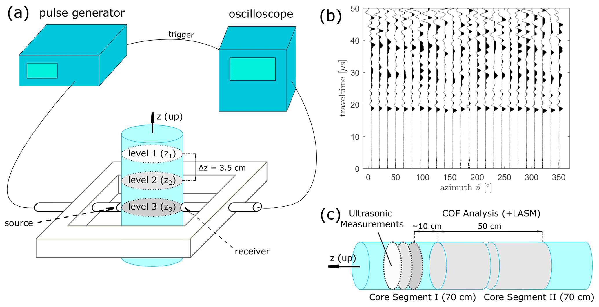
Figure 1(a) Schematic experimental set-up for ultrasonic measurements on the ice core with tools and devices (amplifiers not shown). (b) Example dataset of seismic traces for horizontal measurements. (c) The segmentation of two adjacent ice core segments depicting the position of the ultrasonic and COF analyses.
2.2 Seismic velocities from COF
The hexagonal crystal structure of an ice monocrystal causes an anisotropy in its elastic parameters and therefore affects the propagation velocity of seismic waves. As a result of the crystallographic symmetry, the acoustic velocity parallel to the c axis, which corresponds to the optical axis perpendicular to the basal planes of the ice crystal lattice (e.g. Cuffey and Paterson, 2010) and differs significantly from the velocity in direction of the basal plane. This seismic anisotropy of an ice crystal is fully described by the fourth order elasticity tensor (e.g. Aki and Richards, 2002). The velocity of an acoustic wave with any inclination and azimuthal direction can be calculated analytically (Tsvankin, 2001) provided the mass density of ice is known.
Due to the symmetry relations (Voigt, 1910) the 81 unknown elements of the tensor can be reduced to 21 elements. The hexagonal symmetry of ice further reduces the number of independent constants to five for a monocrystal. For the determination of a representative elasticity tensor for a polycrystalline medium, we follow the approach of Kerch et al. (2018).
The theoretical framework calculates the effective elasticity tensor and derives the seismic velocities from this tensor. Then, the velocities are derived by solving the Christoffel equation (e.g. Tsvankin, 2001, chap. 1.1.2). According to Maurel et al. (2016), this approach for an effective elasticity tensor provides more accurate results (at least for some specific textures) than the complementary velocity averaging method (i.e. calculating the velocities for the individual crystals and computing the average velocity for the polycrystalline medium afterwards). Here, we only summarise the key points for calculating the effective elasticity tenor:
-
This approach is based on an earlier study of Diez and Eisen (2015). However, the framework of Diez and Eisen (2015) relies on particular COF patterns, such as a thick and partial girdle or a single maximum structure, and their representation through the eigenvalues of the orientation tensor. Kerch et al. (2018) do not presume specific COF patterns, which makes it most suitable for our dataset.
-
It then considers the elements of a monocrystal tensor Cm precisely determined in laboratory experiments. In our study, we used the elasticity tensor of Bennett,
calculated by Bennett (1968) for ∘C. This provides the best agreement between our calculated and measured data in both our study and in earlier experiments (Diez et al., 2015, their Table 1).
-
For each ice grain i the monocrystal tensor Cm is transformed into
where Rϑ is the rotational matrix around the vertical axis, Rφ is the rotational matrix around geographic north, and ϑ and φ are the azimuth and the colatitude angle of the grain i, respectively. This aligns the elasticity tensor with the coordinate system of the ice core (transformation of the coordinate system).
-
The rotated monocrystal tensors are summed up elementwise as
thereby assuming a superposition of all nG grains and their respective properties. The relative grain sizes are used as weighting factors wG(i) for each grain. The resulting polycrystalline tensor does not have a hexagonal structure anymore but a triclinic structure with 21 independent elements.
-
With the known elastic properties, the Christoffel equation provides the link to analytic solutions for acoustic velocities vp, vSH, and vSV.
The calculations for the polycrystalline tensor and acoustic velocities are described in more detail in Maurel et al. (2015) and Kerch et al. (2018).
The seismic velocities can be calculated from the elasticity tensor or the inverse compliance tensor. Both approaches provide velocity profiles oscillating around an upper (Voigt bound) and lower (Reuss bound) mean velocity (Hill, 1952). We calculated the seismic velocities from both tensors to obtain these upper and lower bounds of the potential velocity range and further derived the velocity profile from the Hill tensor (the mean of elasticity and compliance tensor). This analytic solution is in agreement with the numerical approach implemented in the Matlab toolbox MTEX (e.g. Mainprice et al., 2011) for crystallographic applications. As the elasticity tensor had been measured at −10 ∘C, we implemented a temperature correction of −2.3 based on Kohnen (1974) to compare the calculated velocities with the velocities derived from ultrasonic measurements (which were measured at −5 ∘C as described below) or in situ seismic data (around −0.5 ∘C).
2.3 Ultrasonic experiments on ice core samples
The dominating COF causes an acoustic velocity anisotropy, and this anisotropy can be verified and quantified by direct laboratory measurements. These measurements were conducted in the cold laboratory at WSL Institute for Snow and Avalanche Research (SLF), Davos.
The orientation of each individual ice core segment was marked at the time of drilling based on mechanical onsets and supporting magnetometric measurements. This ensures a comparison between COF, ultrasonic measurements, and glacier flow at all depths. The temperature for the ultrasonic measurements was chosen to be at ∘C. This is a compromise between temperate ice conditions and a controlled cold environment in order to avoid melting effects during the measurement.
An ultrasonic point-contact (PC) transducer transmitted an acoustic signal into the ice. This signal was recorded by a second transducer on the opposite side of the core. In the current experimental set-up only measurements parallel and perpendicular to the vertical axis of the ice core (colatitude φ=0 and 90∘) were considered. The azimuthal coverage for φ = 90∘ was Δϑ=15 between 0 and 345∘.
Figure 1a shows the experimental set-up that consists of a pulse generator, an oscilloscope, and a set of point-contact transducers. The pulse generator (LeCroy wave station) was employed to generate a pulse with a dominant frequency of 1 MHz and a repetition rate of 10 ms. This electric signal was amplified (amplifiers not shown in Fig. 1a), and a point-contact transducer converted it into an acoustic signal and transmitted it into the ice. This transducer was manufactured in-house at ETH Zurich and provides a stable and highly repeatable sources over a wide range of radiation angles due to its broadband instrument response. This instrument response was calculated in advance using the capillary fracture methods described in Selvadurai (2019). A second transducer (type KRNBB-PC) received and converted the acoustic signal into an electronic pulse, which was transferred to a digital oscilloscope (LeCroy WaveSurfer 3024). For each measurement, we stacked at least 20 individual waveforms to enhance the signal-to-noise ratio. Since the amplifiers caused delays, we determined the actual zero-time of the entire system by a regression through repeated measurements on steel cylinders with precisely determined lengths. These calibration measurements were performed at least twice a day under identical temperature conditions.
The transducers were screwed in an aluminium tube which was held by an aluminium frame with an inner diameter of 90 mm in which the ice core with a variable diameter (average diameter: 68 ± 0.36 mm) was placed. Due to the thermal drilling method, thin water layers refroze along the ice core surface, which led to a rough and partially concave surface. This uneven surface and the limited height of the transducer's tip resulted in a poor coupling, and we removed the outermost 3 mm thin ice layer (i.e. this meltwater “skin”) by lathing the sample. The ice core diameter was then determined manually for each individual measurement. In addition to the horizontal measurements, vertical measurements were performed (average length of the samples: 70.6±1.3 mm). The 1 MHz source pulse generated signals with wavelengths of ≈ 3.8 mm. This resulted in a sample size to wavelength ratio of approximately 20. Thus, the wavelength is small enough to measure an integrated seismic velocity. This velocity can be regarded as the integrated velocity of the individual grain velocities. Much larger wavelengths may introduce geometric issues such as stationary waves which are not representative of acoustic waves travelling through the glacier and thus would later inhibit a comparison with in situ data. However, even with such small wavelengths, some measurements may be biased by only a few larger grains present in these samples of temperate ice. Therefore, we performed measurements at three levels of the ice core samples (denoted as zi, in Fig. 1a, offset Δz ≈ 35 mm) and averaged the results. We assume this stacking procedure to be comparable with the combination of several thin sections for the COF analysis.
2.4 X-ray measurements for air content estimation
In addition to the ultrasonic measurements, the porosity (i.e. the volume of air within the ice) was analysed by X-ray micro-computer tomography (CT) scans. For the scanning and analysis, we followed the same procedures previously adopted for bubbly ice from Dome C (Fourteau et al., 2019). The samples placed within the CT scanner had a diameter of approximately 18 mm and a length of 70 mm resulting in images with a resolution (voxel size) of (10 µm)3 (Gerling et al., 2017). A set of 2–3 regions of interest (ROIs) with a maximum height of 15 mm each was defined in the vicinity of the horizontal levels of ultrasonic measurements, which were about 35 mm apart. The greyscale images of the ROIs were automatically segmented into binary (ice–air) images following the method from Hagenmuller et al. (2013). The air volume fraction was subsequently calculated from the binary images as the fraction of air voxels in the image. The ice core consists mainly of ice and air captured in bubbles. Liquid water was refrozen during storage of the core segments, and dust and sediment particles can be neglected. Therefore, we classify the images as two-phase systems with air bubbles in ice.
3.1 Acoustic velocities inferred from COF
Seven ice core samples, obtained from 2, 22, 33, 45, 52, 65 and 79 m depth, were analysed. The corresponding COF patterns (presented in Fig. 2a–g) are obtained from a set of ice core thin sections from two adjacent ice core segments. They exhibit clear multi-maxima patterns in all samples, consisting of four (five for 65 m) significant clusters of c axes. These clusters always form a “diamond shape” pattern and have been found to be typical for temperate ice with branched, large ice grains. We employed a spherical k-means clustering algorithm (Nguyen, 2020) to determine the individual clusters of grains and their respective centroids. Ice grains that are not assigned to one of the clusters (small black dots in Fig. 2a–g) are not considered for the velocity calculation as they mostly appear within fracture traces (particularly in 22 and 45 m). Further details about the crystal structure are discussed in Hellmann et al. (2021).
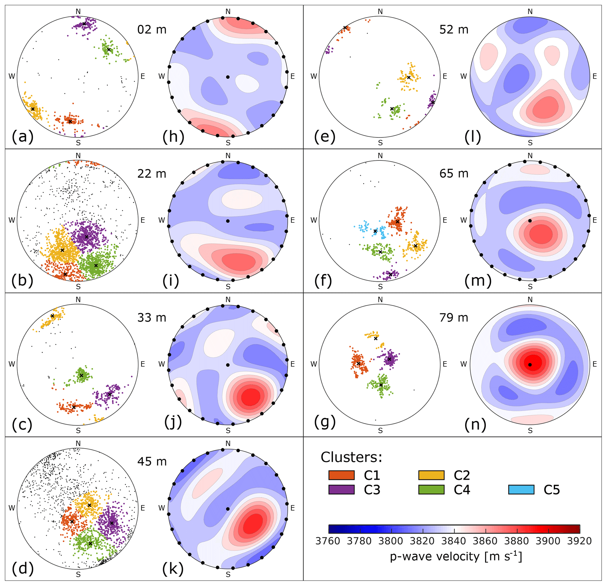
Figure 2COF patterns and calculated seismic velocities for all seven analysed ice core samples: (a–g) c-axis distribution on a lower hemisphere Schmidt plot (the core's vertical axis aligns with the centre of the plot). The grains associated with the individual clusters are colour-coded. (h–n) Seismic P wave velocities (derived from COF, no air correction) for any azimuthal direction and incident angle plotted on a lower hemisphere net. They were plotted with the Matlab toolbox MTEX (Mainprice et al., 2011). The black dots symbolise the sets of angles () for the ultrasonic measurements.
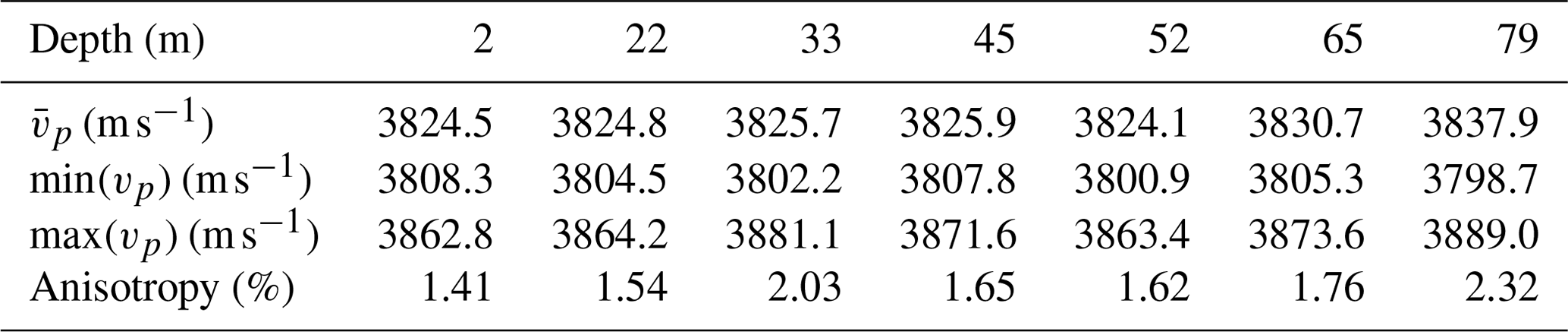
We calculated the acoustic velocities from the COF patterns of all samples. The resulting velocity distributions (Fig. 2h–n) are functions of azimuthal direction and inclination (i.e. colatitude, 0∘ parallel to vertical core axis). The velocities were calculated on a dense grid for azimuth and inclination angles of the incident seismic wave with 1∘ for both angles to avoid interpolation artefacts. The direction of the maximum velocity in each sample coincides in general with the centroid of the multi-maxima cluster (Fig. 8a–g). The exact position of the centroid and thus the velocity maximum depends on the weighting factor that considers the size of the individual ice grains. This may lead to a slight offset between the geometrical midpoint of the diamond-shape pattern and this centroid of the multi-maxima pattern. The minimum velocity is found on a small circle with an opening angle of about 45∘ around the centroid. Perpendicular to the centroid, another minor velocity maximum along a girdle can be observed. The median value of the pure ice velocity per sampling depth lies between 3834 and 3840 m s−1. The anisotropy generally increases with depth (Table 1) and reaches a maximum value of
at 79 m between the global maximum (around vertical direction) and minimum velocity values (Fig. 2n).
The P wave velocity for vertically incident waves (parallel to z axis of the core) increases with depth, especially for the deepest parts where the cluster is centred around the vertical axis (Fig. 3a blue line). The P wave velocities for a colatitude of φ=90∘ (horizontal direction) are shown in Fig. 3b (mean value per sample) and Fig. 4. The largest azimuthal variations appear at 2 m since the c axes of the grains cluster around a horizontally oriented centroid (φc=88.6∘). The maximum horizontal anisotropy is 1.4 %.
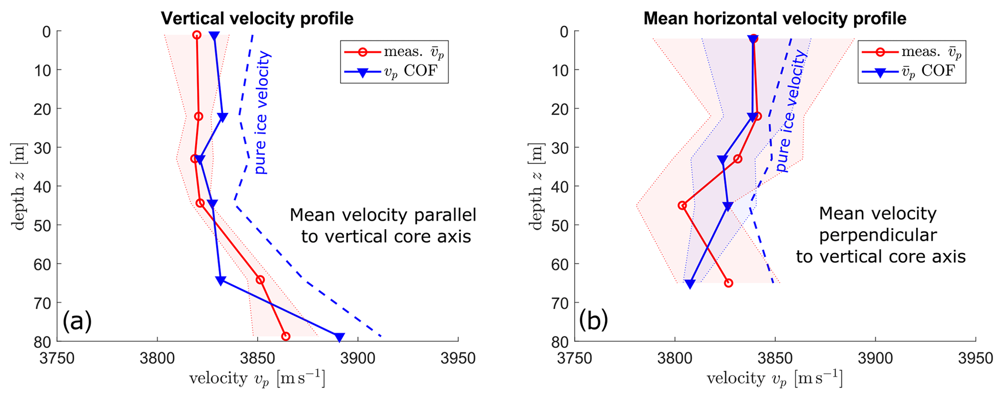
Figure 3Mean values for measured and calculated seismic velocities for (a) vertical, i.e. φ=0∘, and (b) horizontal, i.e. φ=90∘, directions along the ice core. The shaded areas show the standard deviations of the respective measurements. The dashed blue lines show the respective COF-derived velocities without porosity correction.
Table 1Mean, minimum, and maximum calculated P wave velocities (i.e. derived from the COF pattern and not from ultrasonic experiments, without air correction) and degree of anisotropy for each COF sample.
3.2 Acoustic velocities from ultrasonic experiments
We measured the acoustic velocities on five of the above-mentioned ice core samples. The ice core samples were taken from 2, 22, 33, 45, and 65 m depth and usually from the upper of the two ice core segments that have been used for the COF analysis (cf. Fig. 1c). The distance between the uppermost COF thin section and the ultrasonic sample is between 5 and 15 cm (with an exception for 65 m with an offset of 60 cm). For each sample, we carried out three individual horizontal measurements of three different levels (indicated as z1, z2, and z3 in Fig. 1a). For the vertical measurements, we obtained one measurement per sample. As there was a half cylinder of ice from the lowermost depth (79 m) available, we also measured the vertical velocity for this sample. The ultrasonic measurements were conducted using different pieces of ice than those used for the COF analysis, and therefore, the actual grain size and distribution remain unknown. The positions of the ultrasonic measurements are marked in Fig. 2 by black dots.
In a first step, the recorded traces were shifted to correct for zero-time t0, and the P wave arrivals (example shown in Fig. 1b) were picked. Additionally, the ice core diameter for each azimuth was measured, and since the core was not perfectly round, the diameter varied by a few millimetres. The velocities for each azimuth were calculated using the ice core diameter and the P wave travel time. We measured the ice core diameter for each measurement individually, and we found no dependence of calculated seismic velocities on the measured ice core diameters.
To ensure data consistency, the reciprocal travel times were compared for quality checks. Rays with opposing azimuths (ϑ and ϑ+180∘) are reciprocal, and the velocity should be identical. Larger deviations (> 30 m s−1) for individual measurements were considered incorrect, and these measurements were removed from the final dataset (in total, 7 out of 315 traces). Finally, the reciprocal traces for the individual horizontal and vertical measurements were combined, and an average velocity for each azimuth was calculated. That is, we only consider an azimuthal range of 0–180∘, and therefore, the horizontal results show a periodicity of 180∘. This processing scheme was applied to all five samples, and the results are summarised in Fig. 4. Minimum and maximum velocities within the stack of repeated measurements for each azimuth are shown as reddish coloured areas.
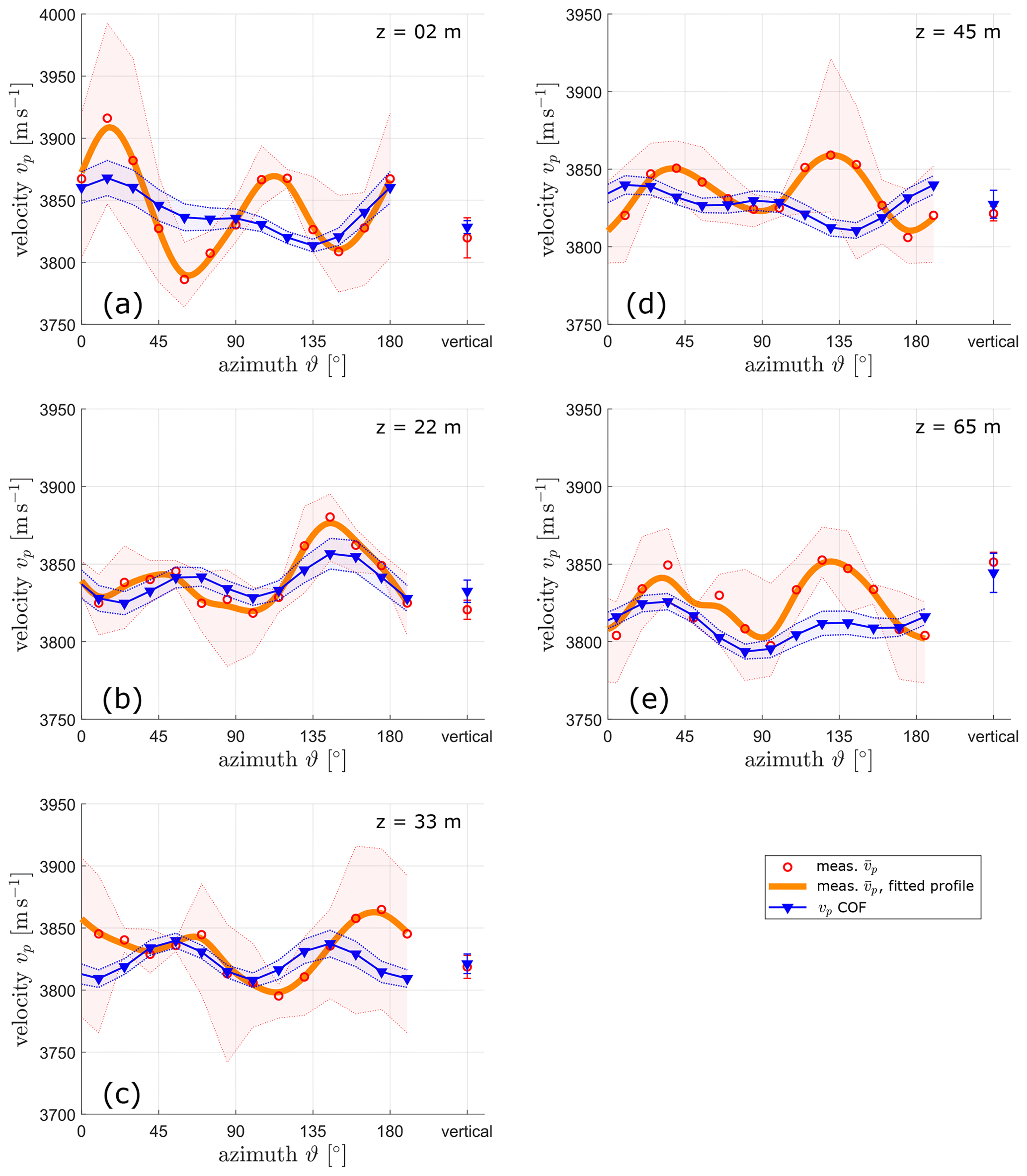
Figure 4Mean measured seismic velocities from ultrasonic experiments (orange curve and red dots) with maximum and minimum values (light red areas) for five ultrasonic samples and the corresponding calculated velocities from the COF distribution (blue curve) from Fig. 2 with Voigt and Reuss bounds. These graphs show the horizontal measurements, φ=90∘. The respective vertical measurement (φ=0∘) is added to each diagram. Depth indicated in upper-right corners.
All five samples show a set of two maxima surrounded by four minima and two local side maxima. For the samples at 2, 22, and 65 m depth the positions of the maxima for measured and COF-derived profiles coincide within a range of a few degrees of azimuth (≤ 15∘; Fig. 4a, b, e). At 33 m, there is a significantly larger azimuthal shift (30∘; Fig. 4c), and for the sample at 45 m maxima of one profile coincide with a minimum of the other (Fig. 4d). The measured velocity profiles show higher amplitudes between maximum and minimum compared to the calculated COF-derived profiles. The COF-derived profiles are in general rather level with smaller differences between the minima and maxima.
3.3 Porosity from X-ray tomography
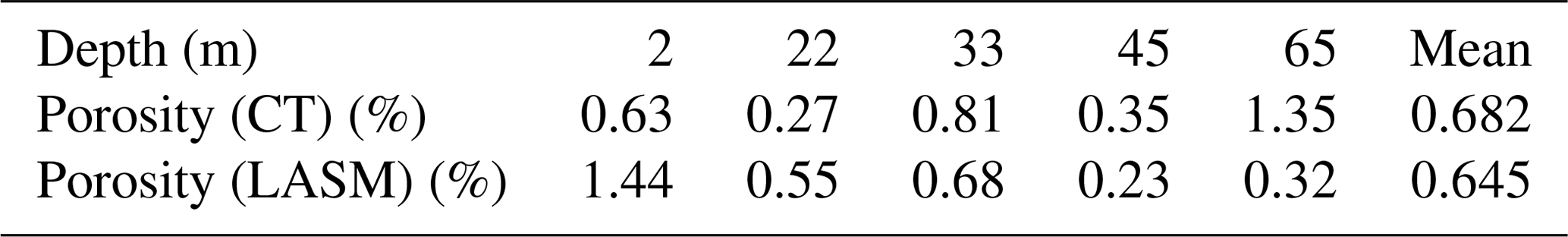
The X-ray CT images provide porosity information in the vicinity of the horizontal ultrasonic measurements (summarised in Table 2). The porosity is governed by air bubble layers in the ice. These air bubble layers show a preferentially horizontal distribution and alternate with air-bubble-free layers along the entire ice core borehole as shown by images of an optical televiewer (OPTV, images not shown). We calculated individual values for each sample and the average porosity over all five samples (0.682 %). An additional porosity analysis based on two-dimensional large-area scanning macroscope (LASM) images (Binder et al., 2013; Krischke et al., 2015), obtained during the thin section preparation, produced similar results (LASM-derived average porosity 0.645 %). In contrast to the porosities from three-dimensional CT measurements, the porosity values determined from the two-dimensional LASM images continuously decrease with increasing depth. This indicates an increasingly heterogeneous distribution of air bubbles in deeper parts of the ice since the porosity values derived from the LASM images are averaged values obtained from 50 cm of ice (Fig. 1c).
The individual CT-derived porosity values (Table 2) are taken into account for the COF-derived vertical velocity profiles in Figs. 3 and 4 (blue curves). This correction reduced the COF-derived velocities by about 30 m s−1 when assuming air-filled spherical bubbles as the second phase (cf. Fig. 3a, dashed magenta line, as an example for uncorrected values). Since we have a relatively low porosity (< 1 %) but do not know the exact size and position of the individual air bubbles, we used a correction for spherical inclusions at a very low volume fraction at which the effective elastic moduli can be calculated exactly (Torquato, 2002, p. 499). The CT and LASM images indicate that the majority of air bubbles not associated with grain boundaries (and therefore not pinned to and affected by the boundary pathways) are spherical, do not show any elongation in certain directions, and therefore confirm our assumption. We retrieved the required bulk and shear moduli of the ice matrix from the corresponding elements of the computed polycrystal elasticity tensor. With these bulk and shear moduli, the CT-derived porosity values, and the mass densities of air (ρ=1.3163 kg m−3 at an ambient temperature of ∘) and ice (ρ=918 kg m−3), we obtained the mean velocities of such a two-phase material. Finally, the difference between this mean velocity and the calculated mean velocities of pure ice was subtracted from the individual velocity values. This correction was applied to the COF-derived profiles (blue curves) in Figs. 3 and 4. The porosity correction causes a shift of the average velocities (see Fig. 3 dashed vs. solid blue lines) but does not affect the shape (i.e. maxima and minima) of the horizontal profiles at the individual depths in Fig. 4.
Table 2Porosity values (%) for each ultrasonic sample (derived from CT measurements) and the corresponding COF thin sections (derived from LASM scans with a vertical offset of 10–15 cm to CT-samples).
4.1 Comparing COF-derived velocity and ultrasonic measurements
The results for COF-derived velocities and the ultrasonic velocity profiles are compared in Figs. 3 and 4. As presented in Sect. 3.3, the COF-derived velocity profiles were corrected for the porosity. The vertical velocities (i.e. parallel to the ice core axis), shown in Fig. 3a, display a relatively good match between the two methods. Likewise, the average horizontal velocity profiles (Fig. 3b) coincide well within the uncertainty ranges. This uncertainty range is defined by the standard deviation around the mean value for all azimuths.
Azimuthal variations in the horizontal measurements are compared in Fig. 4. Only the sample from 22 m depth shows reasonable matching with respect to the positions and amplitudes of the velocity minima and maxima. For all other depths, there are considerably large differences between COF-derived and ultrasonic velocities. It is noteworthy that the sample at 22 m depth exhibits a lower porosity (i.e. lower amount of air bubbles) compared with the remaining samples (Table 2), but the air bubble content cannot fully explain the observed discrepancy between the two velocity profiles shown in Fig. 4. These discrepancies could be caused by the differences in the grain size distribution within the individual samples since we did not conduct both measurements on exactly the same pieces of ice.
Seismic waves have a band-limited frequency content resulting in a finite range of wavelengths. As indicated in Sect. 2.3, the dominant wavelength for the ultrasonic measurements was approximately 3.8 mm. As a consequence, the seismic waves are not just affected by the medium along an infinitely thin ray path connecting the source and receiver but by a finite volume surrounding the ray path. This volume can be estimated with the first Fresnel volume path (e.g. Williamson and Worthington, 1993). Assuming a homogeneous medium including source position S and receiver position R, a point D is considered to be within the first Fresnel volume when
where l is the direct ray path between source and receiver, n is the order of the Fresnel zone, and λ is the dominant wavelength. The ice grains within this Fresnel volume influence the velocity that is derived from the corresponding ultrasonic measurement. To illustrate the situation, we superimposed in Fig. 5 a Fresnel zone computed from Eq. (2) on one of our thin sections of temperate ice including large grains. Figure 5 shows that not only the size but also the position of the particular grains may influence how significantly grains of the particular clusters affect the final velocity profile for the ultrasonic experiments. If grains of a certain cluster only appear at the margins of the ice volume (e.g. the dark blue grains), only a few measurements are affected by these grains, and thus the overall effect of this cluster is smaller compared to its actual statistical appearance in the ice core volume. The analysis becomes even more complex when considering the shape of the grains. As observed in our core data and also in earlier studies (e.g. Hooke and Hudleston, 1980; Monz et al., 2021) the grains in temperate ice are branched. Furthermore, we also observed a clustering of grains with similar orientation. In particular, small grains surround a larger grain, usually called parent grain, as a result of strain-induced grain boundary migration with nucleation of new grains (called SIBM-N; see Faria et al., 2014). The irregular shape of the grains and the clustering of grains with similar orientation may lead to differences between the two velocity profiles. The Fresnel zone is actually a volume (third dimension not shown in Fig. 5) with the size of a few cubic centimetres. The individual measurements are therefore capturing the full three-dimensional shape of the grains. Furthermore, the Fresnel volume concentrates on a small volume within the sample. The clustering effect due to SIBM-N leads to an over-representation of some clusters within these limited volumes. Thus, these clusters around a few large grains are dominating the measured velocity profile. We have qualitatively analysed this effect and were able to find a combination of two or three clusters that reasonably fit into the actual measured ultrasonic velocity profile. However, several combinations of these four clusters led to similar results, and we assume that the fit might also be a statistical effect. We could not find a profound physical explanation. Ultrasonic measurements followed by a COF analysis on the same piece of ice are required to analyse this further.
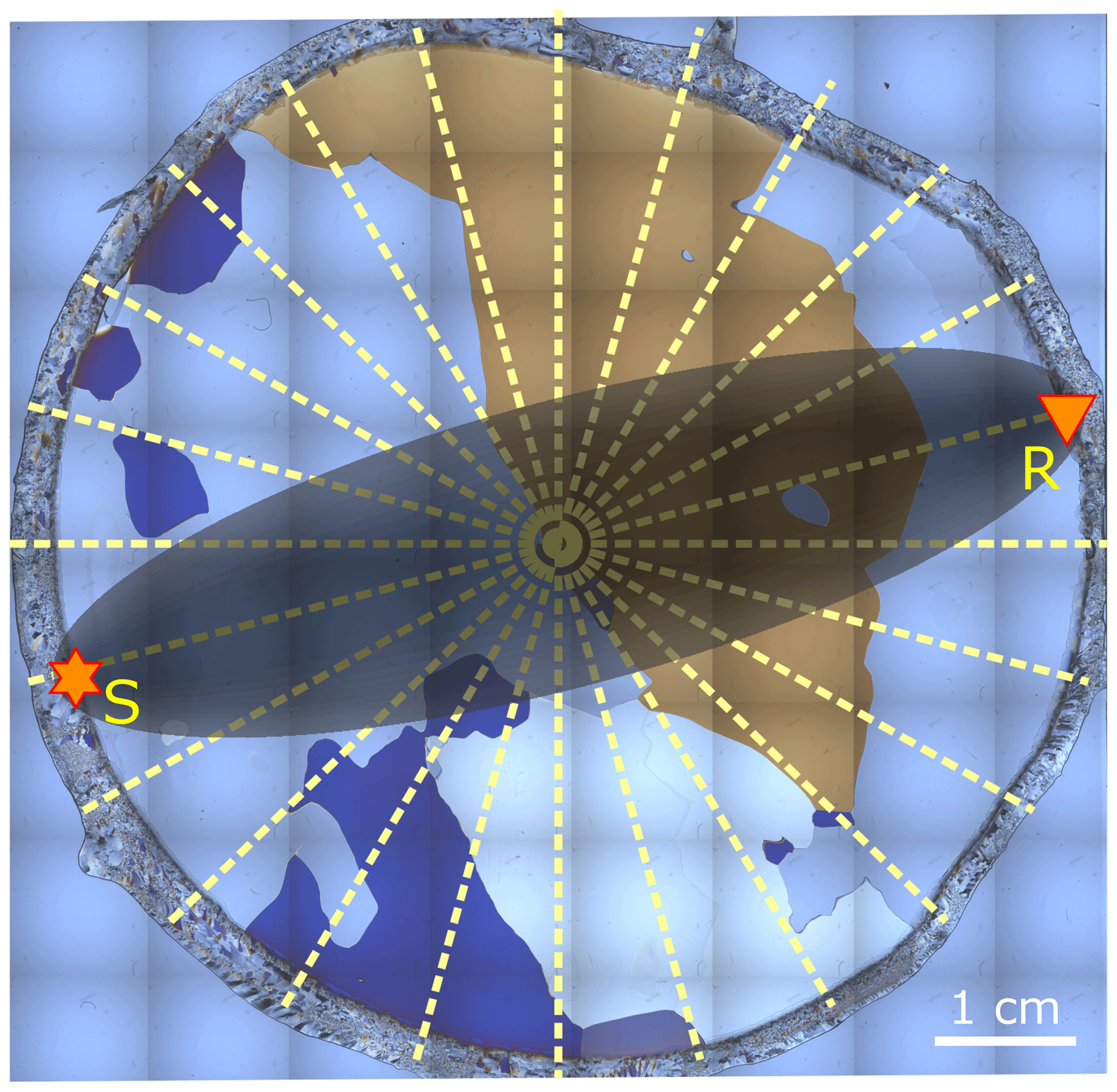
Figure 5Raw image from fabric analyser, showing a typical grain distribution found in the temperate ice core. The coverage by ultrasonic measurements (dashed lines) and an example for the first Fresnel zone (homogeneous medium approximation) are superimposed: S is the sending transducer, and R is the receiver. The distance between source and receivers is ≈ 7 cm on average.
In contrast to the ultrasonic measurements, the thin sections for the COF-derived velocity profiles only provide limited information in the third dimension. This is even more important for an estimated guess of the size of such branched and large grains. Grains close to the thin section but out of plane are invisible for the COF-derived velocity profiles. Furthermore, a cut through a large branched grain may make this grain appear as several small grains, usually called island grains (see Monz et al., 2021, their Fig. 3). A large grain is then underrepresented in the COF-derived profiles but is more prominent in the Fresnel volume and therefore more prominent in the velocities measured by the ultrasonic method. This can be regarded as an out-of-plane effect when comparing ultrasonic and COF-derived profiles. To reduce this off-plane effect, we have always combined sets of three thin sections perpendicular to each other (see Hellmann et al., 2021, their Fig. 4) to obtain the COF-derived profiles. As a consequence, the actual number of grains included in the calculations for the COF-derived profiles differs significantly from the number of grains included in the individual ultrasonic measurements, in which a few branched large grains may be quite prominent in the actual measured ice volume (see Fig. 5).
Therefore, the velocities of COF analysis and the ultrasonic measurements are expected to be different in the presence of large grains. Conversely, a good match can be expected when a large number of small grains is involved. To investigate this further, we computed grain size distributions (Fig. 6) using all thin sections prepared for the COF analysis (Hellmann et al., 2021). Clearly, the sample at 22 m depth shows the largest number of grains and thus the smallest mean grain size. Considering the previous discussion, it is therefore not surprising that we observe a relatively good match in Fig. 4 for this sample and larger discrepancies for the remaining samples.
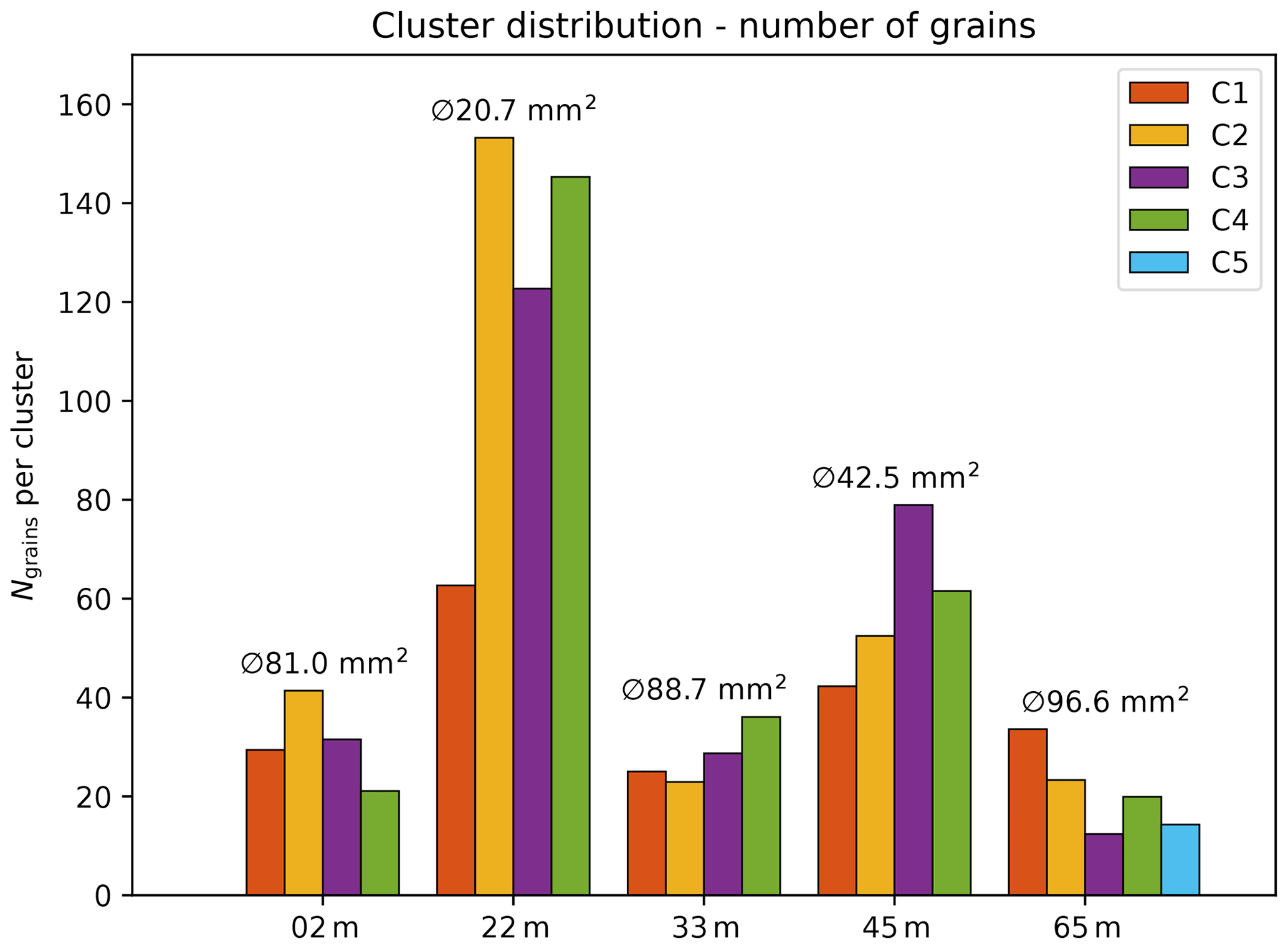
Figure 6Number of grains over all clusters in the individual samples. The mean grain size ⊘ per sample is noted above. The clusters are colour-coded according to Fig. 2.
As a result of the previous discussion, we also assume that a larger amount of ultrasonic measurement levels should lead to a better match with the statistically averaged profile from the COF analysis. Additional ultrasonic measurements are available for the sample of 33 m. These measurements were obtained on the neighbouring core segment just below the analysed COF samples (the original ultrasonic measurements, shown again in Fig. 7a, were acquired above the COF samples). When considering the additional measurements, the differences between the mean velocity profiles derived from COF analyses and ultrasonic measurements further decrease (Fig. 7b). In turn, when considering only a subset of thin sections (here only the four horizontal thin sections) to derive the velocity profile, it also converges to the ultrasonic profile (Fig. 7c).
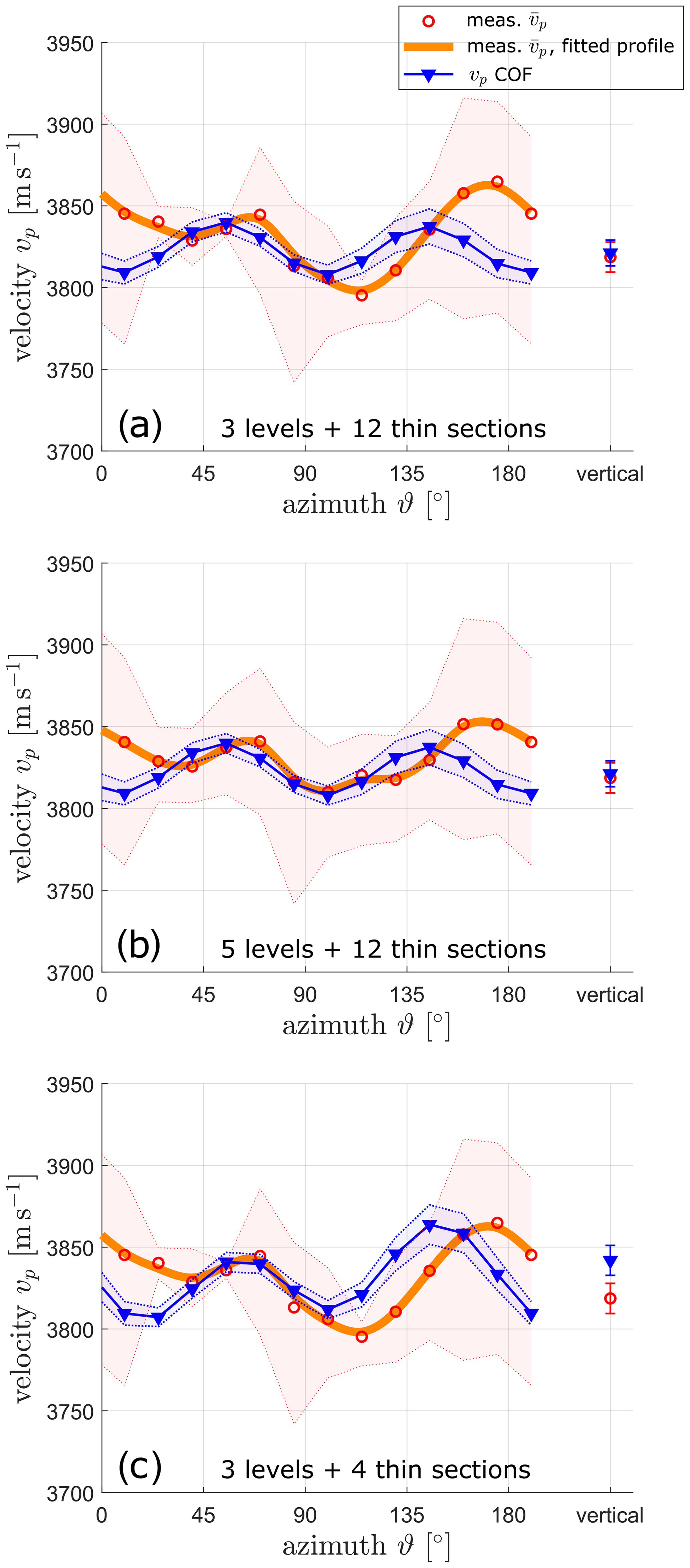
Figure 7Mean measured seismic velocities from ultrasonic experiments (orange curve and red dots) and the corresponding calculated velocities from the COF distribution (blue curve) for the sample at 33 m: (a) same as Fig. 4c, (b) with a larger amount of ultrasonic measurements, and (c) with a smaller amount of thin sections considered for the calculated COF-derived velocity profile.
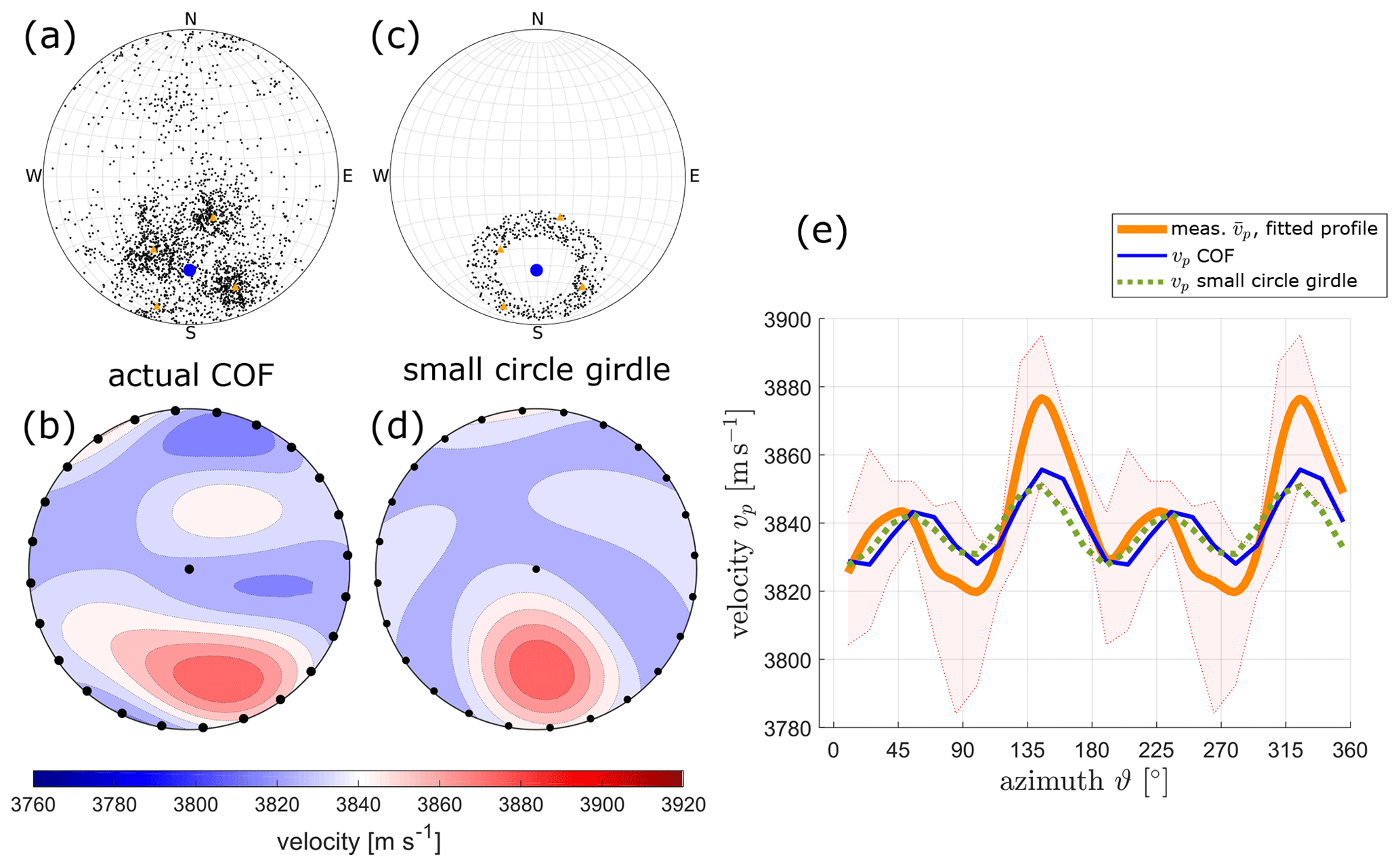
Figure 8Comparison of different fabric types and their velocity profiles for different inclination angles: (a) lower hemisphere Schmidt plots for actual multi-maxima fabric for the sample from 22 m and (b) the derived acoustic velocity pattern for (a). (c) Lower hemisphere Schmidt plots for a modelled small circle girdle fabric and (d) the derived acoustic velocity pattern for (c). The black dots in (b) and (d) symbolise the horizontal and vertical measurement positions. (e) The velocity profiles for horizontal measurements: orange line – actual measured profile, blue line – velocity profile of actual COF, and dashed green line – potential velocity profile for a small circle girdle.
To conclude, ultrasonic and COF analyses complement each other. The first is a deterministic approach allowing for a detailed analysis of a particular ice core volume of a few cubic centimetres. The latter is a statistical approach that provides an integrated COF pattern derived from several centimetre-long (up to 50 cm) ice core samples and thus an averaged velocity. However, both methods are most likely comparable when the numbers of grains are similar in both samples. Hence, both methods should be combined, and ultrasonic measurements may become a valuable technique to support the existing method.
4.2 Ambiguities with other COF patterns
In this study, the COF patterns are assumed to be known a priori, and the ultrasonic results could be correlated with this known COF. The question that arises is if ultrasonic measurements are a suitable method to determine unambiguously unknown COF patterns?
To address this question, we consider the sample at 22 m depth. Its resulting COF and the associated velocity distribution, already shown in Fig. 2b and i, are shown again in Fig. 8a and b. For this sample, the small grain size prerequisite is met, leading to a good match between COF-derived and ultrasonic velocity profiles (Fig. 4b, shown again in Fig. 8e without uncertainty ranges). We now compare the results with a small circle girdle structure (Fig. 8c), which is a common COF pattern for compressional deformation in combination with recrystallisation (Wallbrecher, 1986). Its corresponding velocity distribution is shown in Fig. 8d. When only considering the horizontal orientations, as measured with our ultrasonic experimental set-up (marked with black dots in Fig. 8b and d), the azimuthal velocity variations of both, the actual “diamond shape” pattern (blue curve in Fig. 8e) and the small circle girdle (dashed green curve in Fig. 8e), are compatible with the measured ultrasonic data (orange curve in Fig. 8e). Obviously, there exist several COF structures that explain the ultrasonic data equally well, thereby leading to ambiguities and uncertainties in interpreting the ultrasonic data. Similar ambiguities can be observed for COF patterns typical for polar ice such as single maximum vs. girdle fabrics. Adding the additional vertical measurement parallel to the core axis (black dot in the centre of Fig. 8b and d) does not remove this ambiguity for the small-girdle example.
To further reduce this ambiguity, adding additional ultrasonic measurements spanning a range of azimuths and inclinations such that the area of the stereoplots would be sampled more regularly would be required. With modern point-contact transducers, it seems to be feasible to implement such an experimental layout with a reasonable expenditure of time when using a multi-channels recording system.
These ambiguities show that COF analyses will also be required in the future, but ultrasonic measurements can support this analysis and bridge the gaps between the discrete COF samples. Finally, ultrasonic measurements on ice cores and in boreholes provide the link between COF and surface geophysical velocities (Bentley, 1972; Gusmeroli et al., 2012; Diez et al., 2014).
Our measurement scheme (Fig. 1a) was built for first attempts at investigating the feasibility of ultrasonic measurements to detect the COF along an ice core and to establish a link between COF and cross-borehole or surface seismic experiments. Although we showed that there are ambiguities, such a device provides valuable information and could directly be employed in situ on freshly drilled ice cores. As an advantage of an immediate measurement on thermally drilled ice cores, one would avoid the refreezing of meltwater and thus have a much better coupling of the transducers without extra work for removing this meltwater “skin”. For mechanically drilled cores with a relatively convex shape, the point-contact transducers are expected to be well coupled. Furthermore, more than two transducers are recommended to obtain several inclined measurements as discussed above, and the transducers should further be pressed onto the ice with a defined constant pressure. A constant pressure is relevant to avoid any pressure melting effects, and it ensures identical coupling conditions. This enhances the comparability of the acoustic signals throughout the entire experiment.
In addition, the determination of the exact distance between source and receiver should be automated. A manual measurement of the distances, as performed in our experiments, leads to a higher uncertainty in the derived velocities. Moreover it is not feasible with several transducers. These improvements require a more comprehensive measurement device. Such a device could be employed in a processing line (e.g. in polar ice core drilling projects) with existing devices such as for dielectric profiling (DEP) (Wilhelms et al., 1998) before cutting the ice core into sub-samples for different analyses. As it also allows for a fast data acquisition, such a device could also be employed for other purposes such as detecting the link between two neighbouring ice core segments (i.e. retrieving the actual orientation of the freshly drilled segment within the glacier).
We have performed ultrasonic experiments on ice cores from a temperate glacier, and we compared the results with those from a well-established COF analysis method. The main objectives of this study were (i) to compare the ultrasonic and COF-derived seismic velocities and (ii) to check if ultrasonic measurements have the potential to replace or reduce the labour-intensive and destructive COF analysis. Our main findings can be summarised as follows:
-
Ultrasonic and COF-derived seismic velocities are comparable when the grain size of the ice crystals is sufficiently small. However, this condition is generally not met in temperate ice. As a consequence, we recommend applying this method to cold (e.g. polar) ice cores with small grains.
-
In the presence of large grains, we observe a poor correlation between the ultrasonic and COF-derived velocities. The ultrasonic measurements belong to the deterministic approaches. Each measurement samples the actual three-dimensional volumes (Fresnel volumes) and only considers the grains therein. The COF-derived profiles provide a statistical mean value of the velocities for all thin sections. Therefore, the number of measurement levels of ultrasonic measurements needs to be sufficiently large. This is especially relevant for samples from temperate ice cores.
-
In the presence of a significant porosity (i.e. air bubbles), a correction needs to be applied to make ultrasonic and COF-derived velocities comparable. This requires the determination of the porosity. In this study, we have employed a CT scanner for that purpose.
-
In principle, ultrasonic measurements can be employed for determining COF patterns. However, this requires a relatively dense sampling of the ice core, including a broad range of azimuths and inclination angles. Our experimental set-up, including only horizontal and vertical measurements, led to ambiguous results.
On the basis of our findings, we conclude that ultrasonic measurements are not yet an adequate replacement for COF analysis. However, since the development of ultrasonic transducers is progressing rapidly, we judge it feasible that adequate experimental layouts of ultrasonic experiments can be implemented in the foreseeable future. This would offer substantial benefits since it would reduce the labour-intensive COF analysis. Furthermore, the ultrasonic measurements offer the significant advantage of being non-destructive, and the samples of the generally valuable ice cores would remain available for other analyses of physical properties. This also means that the ultrasonic measurements can continuously be obtained on freshly drilled cores. Nevertheless, a certain but reduced number of thin sections for a COF analysis can still be used to calibrate the ultrasonic data and to dispose of ambiguities with direct comparisons of the results of both methods from the same ice core samples.
The ice fabric data and the LASM images are published in the open-access database PANGAEA® (https://doi.org/10.1594/PANGAEA.888518, Hellmann et al., 2018a; https://doi.org/10.1594/PANGAEA.888517, Hellmann et al., 2018b). The ultrasonic data are available in the open-access database ETH Research Collection (https://doi.org/10.3929/ethz-b-000453859, Hellmann et al., 2020).
This study was initiated and supervised by HM, AB, and IW. SH, JK, and IW analysed the ice core microstructure to obtain the COF and calculate the seismic velocities. SH, MG, and HL planned and conducted the ultrasonic and CT measurements. Data processing and calculations were made by SH with support from all co-authors. The paper was written by SH, with comments and suggestions for improvements from all co-authors.
The authors declare that they have no conflict of interest.
Publisher's note: Copernicus Publications remains neutral with regard to jurisdictional claims in published maps and institutional affiliations.
The data acquisition for this project has been provided by the Paul-Scherrer Institute, Villingen, the Alfred Wegener Institute Helmholtz Centre for Polar and Marine Research, Bremerhaven, and WSL Institute for Snow and Avalanche Research SLF, Davos. We especially thank Matthias Jaggi, Paul Selvadurai, and Claudio Madonna for their extensive technical and scientific support for the ultrasonic measurements and the equipment provided and Theo Jenk, Margit Schwikowski, and Jan Eichler for their support during ice core drilling and processing. We acknowledge Kenichi Matsuoka for the editorial work and the reviewers Valerie Maupin and Sridhar Anandakrishnan for their helpful comments.
This research has been supported by the Schweizerischer Nationalfonds zur Förderung der Wissenschaftlichen Forschung (grant nos. 200021_169329/1 and 200021_169329/2).
This paper was edited by Kenichi Matsuoka and reviewed by Valerie Maupin and Sridhar Anandakrishnan.
Aki, K. and Richards, P. G.: Quantitative Seismology, Quantitative Seismology, edited by: Aki, K. and Richards, P. G.. University Science Books, 2nd Edn., ISBN 0-935702-96-2, 704pp, 2002. a
Alley, R. B.: Fabrics in Polar Ice Sheets: Development and Prediction, Science, 240, 493–495, 1988. a
Alley, R. B.: Flow-Law Hypotheses for Ice-Sheet Modeling, J. Glaciol., 38, 245–256, 1992. a
Anandakrishnan, S., Fltzpatrick, J. J., Alley, R. B., Gow, A. J., and Meese, D. A.: Shear-Wave Detection of Asymmetric c-Axis Fabrics in the GISP2 Ice Core, Greenland, J. Glaciol., 40, 491–496, https://doi.org/10.3189/S0022143000012363, 1994. a
Azuma, N.: A Flow Law for Anisotropic Ice and Its Application to Ice Sheets, Earth Planet Sc. Lett., 128, 601–614, https://doi.org/10.1016/0012-821X(94)90173-2, 1994. a
Azuma, N. and Higashi, A.: Mechanical Properties of Dye 3 Greenland Deep Ice Cores, Ann. Glaciol., 5, 1–8, 1984. a
Bennett, H. F.: An Investigation into Velocity Anisotropy through Measurements of Ultrasonica Wave Velocities in Snow and Ice Cores from Greenland and Antarctica(Investigation into Velocity Anisotropy through Measurements of Ultrasonic Wave Velocities in Snow and Ice Cores from Greenland and Antarctica), PhD Thesis, University of Wisconsin-Madison, 1968. a
Bentley, C. R.: Seismic-Wave Velocities in Anisotropic Ice: A Comparison of Measured and Calculated Values in and around the Deep Drill Hole at Byrd Station, Antarctica, J. Geophys. Res., 77, 4406–4420, https://doi.org/10.1029/JB077i023p04406, 1972. a, b
Bentley, C. R.: Advances in Geophysical Exploration of Ice Sheets and Glaciers, J. Glaciol., 15, 113–135, https://doi.org/10.3189/S0022143000034328, 1975. a
Binder, T., Garbe, C. S., Wagenbach, D., Freitag, J., and Kipfstuhl, S.: Extraction and Parametrization of Grain Boundary Networks in Glacier Ice, Using a Dedicated Method of Automatic Image Analysis, J. Microsc., 250, 130–141, https://doi.org/10.1111/jmi.12029, 2013. a
Blankenship, D. D. and Bentley, C. R.: The Crystalline Fabric of Polar Ice Sheets Inferred from Seismic Anisotropy, IAHS Publ., 170, 17–28, 1987. a
Brisbourne, A. M., Martín, C., Smith, A. M., Baird, A. F., Kendall, J. M., and Kingslake, J.: Constraining Recent Ice Flow History at Korff Ice Rise, West Antarctica, Using Radar and Seismic Measurements of Ice Fabric, J. Geophys. Res.-Earth, 124/1, 175–194, https://doi.org/10.1029/2018JF004776, 2019. a
Budd, W. F.: The Development of Crystal Orientation Fabrics in Moving Ice, Z. Gletscherkd. Glazialgeol., 8, 65–105, 1972. a, b
Budd, W. F. and Jacka, T. H.: A Review of Ice Rheology for Ice Sheet Modelling, Cold Reg. Sci. Technol., 16, 107–144, https://doi.org/10.1016/0165-232X(89)90014-1, 1989. a
Cuffey, K. M. and Paterson, W. S. B.: The Physics of Glaciers, 4th Edn., Elsevier, Amsterdam, 2010. a
Diez, A. and Eisen, O.: Seismic wave propagation in anisotropic ice – Part 1: Elasticity tensor and derived quantities from ice-core properties, The Cryosphere, 9, 367–384, https://doi.org/10.5194/tc-9-367-2015, 2015. a, b, c
Diez, A., Eisen, O., Weikusat, I., Eichler, J., Hofstede, C., Bohleber, P., Bohlen, T., and Polom, U.: Influence of Ice Crystal Anisotropy on Seismic Velocity Analysis, Ann. Glaciol., 55, 97–106, https://doi.org/10.3189/2014AoG67A002, 2014. a
Diez, A., Eisen, O., Hofstede, C., Lambrecht, A., Mayer, C., Miller, H., Steinhage, D., Binder, T., and Weikusat, I.: Seismic wave propagation in anisotropic ice – Part 2: Effects of crystal anisotropy in geophysical data, The Cryosphere, 9, 385–398, https://doi.org/10.5194/tc-9-385-2015, 2015. a, b
Drews, R., Eisen, O., Steinhage, D., Weikusat, I., Kipfstuhl, S., and Wilhelms, F.: Potential Mechanisms for Anisotropy in Ice-Penetrating Radar Data, J. Glaciol., 58, 613–624, https://doi.org/10.3189/2012JoG11J114, 2012. a
Eichler, J.: C-Axis Analysis of the NEEM Ice Core – An Approach Based on Digital Image Processing, Diploma Thesis, Freie Universität Berlin, 2013. a
Faria, S. H., Weikusat, I., and Azuma, N.: The Microstructure of Polar Ice. Part II: State of the Art, J. Struct. Geol., 61, 21–49, https://doi.org/10.1016/j.jsg.2013.11.003, 2014. a, b
Fourteau, K., Martinerie, P., Faïn, X., Schaller, C. F., Tuckwell, R. J., Löwe, H., Arnaud, L., Magand, O., Thomas, E. R., Freitag, J., Mulvaney, R., Schneebeli, M., and Lipenkov, V. Ya.: Multi-tracer study of gas trapping in an East Antarctic ice core, The Cryosphere, 13, 3383–3403, https://doi.org/10.5194/tc-13-3383-2019, 2019. a
Freitag, J., Wilhelms, F., and Kipfstuhl, S.: Microstructure-Dependent Densification of Polar Firn Derived from X-Ray Microtomography, J. Glaciol., 50, 243–250, https://doi.org/10.3189/172756504781830123, 2004. a
Gerling, B., Löwe, H., and van Herwijnen, A.: Measuring the Elastic Modulus of Snow, Geophys. Res. Lett., 44, 11088–11096, https://doi.org/10.1002/2017GL075110, 2017. a, b
Gillet-Chaulet, F., Gagliardini, O., Meyssonnier, J., Montagnat, M., and Castelnau, O.: A User-Friendly Anisotropic Flow Law for Ice-Sheet Modeling, J. Glaciol., 51, 3–14, https://doi.org/10.3189/172756505781829584, 2005. a
Graham, F. S., Morlighem, M., Warner, R. C., and Treverrow, A.: Implementing an empirical scalar constitutive relation for ice with flow-induced polycrystalline anisotropy in large-scale ice sheet models, The Cryosphere, 12, 1047–1067, https://doi.org/10.5194/tc-12-1047-2018, 2018. a
Gusmeroli, A., Pettit, E. C., Kennedy, J. H., and Ritz, C.: The Crystal Fabric of Ice from Full-Waveform Borehole Sonic Logging: Borehole sonic logging in ice sheets, J. Geophys. Res.-Earth, 117, F03021, https://doi.org/10.1029/2012JF002343, 2012. a, b
Hagenmuller, P., Chambon, G., Lesaffre, B., Flin, F., and Naaim, M.: Energy-Based Binary Segmentation of Snow Microtomographic Images, J. Glaciol., 59, 859–873, https://doi.org/10.3189/2013JoG13J035, 2013. a
Hellmann, S., Kerch, J., Eichler, J., Jansen, D., Weikusat, I., Schwikowski, M., Bauder, A., and Maurer, H.: Crystal C-Axes Measurements (Fabric Analyser G50) of Ice Core Samples Collected from the Temperate Alpine Ice Core Rhone_2017, PANGAEA, https://doi.org/10.1594/PANGAEA.888518, 2018a. a
Hellmann, S., Kerch, J., Eichler, J., Jansen, D., Weikusat, I., Schwikowski, M., Bauder, A., and Maurer, H.: Large Area Scan Macroscope Images of Ice Core Samples Collected from the Temperate Alpine Ice Core Rhone_2017, PANGAEA, https://doi.org/10.1594/PANGAEA.888517, 2018b. a
Hellmann, S., Grab, M., Jaggi, M., Löwe, H., and Bauder, A.: Acoustic Ultrasound Measurements on Ice Core Samples from Rhonegletscher, ETH Zurich, https://doi.org/10.3929/ethz-b-000453859, 2020. a
Hellmann, S., Kerch, J., Weikusat, I., Bauder, A., Grab, M., Jouvet, G., Schwikowski, M., and Maurer, H.: Crystallographic analysis of temperate ice on Rhonegletscher, Swiss Alps, The Cryosphere, 15, 677–694, https://doi.org/10.5194/tc-15-677-2021, 2021. a, b, c, d, e
Hill, R.: The Elastic Behaviour of a Crystalline Aggregate, Proc. Phys. Soc. A, 65, 349–354, https://doi.org/10.1088/0370-1298/65/5/307, 1952. a
Hooke, R. L. and Hudleston, P. J.: Ice Fabrics in a Vertical Flow Plane, Barnes Ice Cap, Canada, J. Glaciol., 25, 195–214, https://doi.org/10.3189/S0022143000010443, 1980. a, b
Jordan, T. M., Schroeder, D. M., Castelletti, D., Li, J., and Dall, J.: A Polarimetric Coherence Method to Determine Ice Crystal Orientation Fabric From Radar Sounding: Application to the NEEM Ice Core Region, IEEE T. Geosci. Remote, 57, 8641–8657, https://doi.org/10.1109/TGRS.2019.2921980, 2019. a
Kerch, J., Diez, A., Weikusat, I., and Eisen, O.: Deriving micro- to macro-scale seismic velocities from ice-core c axis orientations, The Cryosphere, 12, 1715–1734, https://doi.org/10.5194/tc-12-1715-2018, 2018. a, b, c, d, e
Kluskiewicz, D., Waddington, E. D., Anandakrishnan, S., Voigt, D. E., Matsuoka, K., and McCarthy, M. P.: Sonic Methods for Measuring Crystal Orientation Fabric in Ice, and Results from the West Antarctic Ice Sheet (WAIS) Divide, J. Glaciol., 63, 603–617, https://doi.org/10.1017/jog.2017.20, 2017. a
Kohnen, H.: The Temperature Dependence of Seismic Waves in Ice, J. Glaciol., 13, 144–147, 1974. a
Krischke, A., Oechsner, U., and Kipfstuhl, S.: Rapid Microstructure Analysis of Polar Ice Cores, Optik & Photonik, 10, 32–35, https://doi.org/10.1002/opph.201500016, 2015. a
Langway, C. C., Shoji, H., and Azuma, N.: Crystal Size and Orientation Patterns in the Wisconsin-Age Ice from Dye 3, Greenland, Ann. Glaciol., 10, 109–115, https://doi.org/10.3189/S0260305500004262, 1988. a
Mainprice, D., Hielscher, R., and Schaeben, H.: Calculating Anisotropic Physical Properties from Texture Data Using the MTEX Open-Source Package, Geol. Soc. Spec. Publ., 360, 175–192, https://doi.org/10.1144/SP360.10, 2011. a, b
Matsuoka, K., Furukawa, T., Fujita, S., Maeno, H., Uratsuka, S., Naruse, R., and Watanabe, O.: Crystal Orientation Fabrics within the Antarctic Ice Sheet Revealed by a Multipolarization Plane and Dual-Frequency Radar Survey, J. Geophys. Res.-Sol. Ea., 108, 2499, https://doi.org/10.1029/2003JB002425, 2003. a
Maurel, A., Lund, F., and Montagnat, M.: Propagation of Elastic Waves through Textured Polycrystals: Application to Ice, P. Roy. Soc. A, 471, 20140988, https://doi.org/10.1098/rspa.2014.0988, 2015. a, b
Maurel, A., Mercier, J.-F., and Montagnat, M.: Critical investigation of calculation methods for the elastic velocities in anisotropic ice polycrystals, The Cryosphere, 10, 3063–3070, https://doi.org/10.5194/tc-10-3063-2016, 2016. a
Mikesell, T., van Wijk, K., Otheim, L., Marshall, H.-P., and Kurbatov, A.: Laser Ultrasound Observations of Mechanical Property Variations in Ice Cores, Geosciences, 7, 47, https://doi.org/10.3390/geosciences7030047, 2017. a
Monz, M. E., Hudleston, P. J., Prior, D. J., Michels, Z., Fan, S., Negrini, M., Langhorne, P. J., and Qi, C.: Full crystallographic orientation (c and a axes) of warm, coarse-grained ice in a shear-dominated setting: a case study, Storglaciären, Sweden, The Cryosphere, 15, 303–324, https://doi.org/10.5194/tc-15-303-2021, 2021. a, b, c
Nanthikesan, S. and Sunder, S.: Anisotropic Elasticity of Polycrystalline Ice Ih, Cold Reg. Sci. Technol., 22, 149–169, https://doi.org/10.1016/0165-232X(94)90026-4, 1994. a
Nguyen, X. V.: The Spherical K-Means Algorithm, MATLAB Central File Exchange, available at: https://ch.mathworks.com/matlabcentral/fileexchange/32987-the-spherical-k-means-algorithm, last access: 23 July 2020. a
Peternell, M., Kohlmann, F., Wilson, C. J., Seiler, C., and Gleadow, A. J.: A New Approach to Crystallographic Orientation Measurement for Apatite Fission Track Analysis: Effects of Crystal Morphology and Implications for Automation, Chem. Geol., 265, 527–539, https://doi.org/10.1016/j.chemgeo.2009.05.021, 2009. a, b
Pettit, E. C., Thorsteinsson, T., Jacobson, H. P., and Waddington, E. D.: The Role of Crystal Fabric in Flow near an Ice Divide, J. Glaciol., 53, 277–288, https://doi.org/10.3189/172756507782202766, 2007. a
Picotti, S., Vuan, A., Carcione, J. M., Horgan, H. J., and Anandakrishnan, S.: Anisotropy and Crystalline Fabric of Whillans Ice Stream (West Antarctica) Inferred from Multicomponent Seismic Data, J. Geophys. Res.-Sol. Ea., 120, 4237–4262, https://doi.org/10.1002/2014JB011591, 2015. a
Placidi, L., Greve, R., Seddik, H., and Faria, S. H.: Continuum-Mechanical, Anisotropic Flow Model for Polar Ice Masses, Based on an Anisotropic Flow Enhancement Factor, Continuum Mech. Therm., 22, 221–237, https://doi.org/10.1007/s00161-009-0126-0, 2010. a
Schwikowski, M., Jenk, T. M., Stampfli, D., and Stampfli, F.: A New Thermal Drilling System for High-Altitude or Temperate Glaciers, Ann. Glaciol., 55, 131–136, https://doi.org/10.3189/2014AoG68A024, 2014. a
Selvadurai, P. A.: Laboratory Insight Into Seismic Estimates of Energy Partitioning During Dynamic Rupture: An Observable Scaling Breakdown, J. Geophys. Res.-Sol. Ea., 124, 11350–11379, https://doi.org/10.1029/2018JB017194, 2019. a
Torquato, S.: Random Heterogeneous Materials: Microstructure and Macroscopic Properties, 16, in: Interdisciplinary Applied Mathematics, Springer, New York, 2002. a
Tsvankin, I.: Seismic Signatures and Analysis of Reflection Data in Anisotropic Media: Elsevier Handbook of Geophysical Exploration, Pergamon Press, Oxford, 2001. a, b
Voigt, W.: Lehrbuch Der Kristallphysik: Mit Ausschluss Der Kristalloptik, vol. 12 of Bibliotheca Mathematica Teubneriana, Teubner, Leipzig, Berlin, 1st Edn., 1910. a
Wallbrecher, E.: Tektonische Und Gefügeanalytische Arbeitsweisen: Graphische, Rechnerische Und Statistische Verfahren, Enke, Stuttgart, 1986. a
Wilhelms, F.: Explaining the Dielectric Properties of Firn as a Density-and-Conductivity Mixed Permittivity (DECOMP), Geophys. Res. Lett, 32, L16501, https://doi.org/10.1029/2005GL022808, 2005. a
Wilhelms, F., Kipfstuhl, J., Miller, H., Heinloth, K., and Firestone, J.: Precise Dielectric Profiling of Ice Cores: A New Device with Improved Guarding and Its Theory, J. Glaciol., 44, 171–174, https://doi.org/10.3189/S002214300000246X, 1998. a
Williamson, P. R. and Worthington, M. H.: Resolution Limits in Ray Tomography Due to Wave Behavior: Numerical Experiments, Geophysics, 58, 727–735, https://doi.org/10.1190/1.1443457, 1993. a
Wilson, C. J., Russell-Head, D. S., and Sim, H. M.: The Application of an Automated Fabric Analyzer System to the Textural Evolution of Folded Ice Layers in Shear Zones, Ann. Glaciol., 37, 7–17, 2003. a, b