the Creative Commons Attribution 4.0 License.
the Creative Commons Attribution 4.0 License.
 | 17 Oct 2018
A temperature- and stress-controlled failure criterion for ice-filled permafrost rock joints
Philipp Mamot
Samuel Weber
Tanja Schröder
Michael Krautblatter
Instability and failure of high mountain rock slopes have significantly increased since the 1990s coincident with climatic warming and are expected to rise further. Most of the observed failures in permafrost-affected rock walls are likely triggered by the mechanical destabilisation of warming bedrock permafrost including ice-filled joints. The failure of ice-filled rock joints has only been observed in a small number of experiments, often using concrete as a rock analogue. Here, we present a systematic study of the brittle shear failure of ice and rock–ice interfaces, simulating the accelerating phase of rock slope failure. For this, we performed 141 shearing experiments with rock–ice–rock “sandwich”' samples at constant strain rates (10−3 s−1) provoking ice fracturing, under normal stress conditions ranging from 100 to 800 kPa, representing 4–30 m of rock overburden, and at temperatures from −10 to −0.5 ∘C, typical for recent observed rock slope failures in alpine permafrost. To create close to natural but reproducible conditions, limestone sample surfaces were ground to international rock mechanical standard roughness. Acoustic emission (AE) was successfully applied to describe the fracturing behaviour, anticipating rock–ice failure as all failures are predated by an AE hit increase with peaks immediately prior to failure. We demonstrate that both the warming and unloading (i.e. reduced overburden) of ice-filled rock joints lead to a significant drop in shear resistance. With a temperature increase from −10 to −0.5 ∘C, the shear stress at failure reduces by 64 %–78 % for normal stresses of 100–400 kPa. At a given temperature, the shear resistance of rock–ice interfaces decreases with decreasing normal stress. This can lead to a self-enforced rock slope failure propagation: as soon as a first slab has detached, further slabs become unstable through progressive thermal propagation and possibly even faster by unloading. Here, we introduce a new Mohr–Coulomb failure criterion for ice-filled rock joints that is valid for joint surfaces, which we assume similar for all rock types, and which applies to temperatures from −8 to −0.5 ∘C and normal stresses from 100 to 400 kPa. It contains temperature-dependent friction and cohesion, which decrease by 12 % ∘C−1 and 10 % ∘C−1 respectively due to warming and it applies to temperature and stress conditions of more than 90 % of the recently documented accelerating failure phases in permafrost rock walls.
- Article
(8175 KB) - Full-text XML
-
Supplement
(3317 KB) - BibTeX
- EndNote


Rock slope failures in high mountain areas potentially endanger human lives, settlements and alpine infrastructure. The impact of the climate-induced degradation of mountain permafrost on rock slope destabilisation has been inferred from numerous studies in the last 2 decades (Fischer et al., 2006; Gruber et al., 2004; Gruber and Haeberli, 2007; Ravanel and Deline, 2015). The number of failure events has increased since the 1990s coincident with climatic warming; failures influenced by permafrost degradation are expected to respond to a warming climate by more frequent events (Gobiet et al., 2014; Huggel et al., 2012; Ravanel and Deline, 2011). The majority of failures in permafrost-affected rock frequently expose ice-filled joints as potential shear and detachment planes (Dramis et al., 1995; Gruber and Haeberli, 2007; Ravanel et al., 2010), as for example, the recent 3–4×10⁶ m3 rock slope failure at Pizzo Cengalo, Graubünden, Switzerland, on 23 August 2017 (Baer et al., 2017; Beniston et al., 2018; Marcia Phillips, personal communication, 2018). Fractures and fractured zones in mountain bedrock permafrost usually contain ice to depths of several tens of metres (Deline et al., 2015; Gruber and Haeberli, 2007). Ice fillings can contribute to systematically higher shear strengths due to rock–ice interlocking and adhesion and thus increase rock slope stability, especially when the ice is at a low temperature. This bonding of ice-filled joints is reduced or even lost as the temperature increases (Davies et al., 2001; Gruber and Haeberli, 2007).
Rock joints that are located within bedrock permafrost (ground that remains permanently frozen for at least 2 consecutive years; Harris et al., 1988) are referred to as “permafrost rock joints” in this paper. Permafrost conditions are below the maximum thaw depth, which typically ranges between 2 and 8 m in alpine environments (Böckli et al., 2011; Delaloye et al., 2016), and apply to ice-filled rock fractures, rock pores and microfractures (Gruber and Haeberli, 2007). In this paper, both “joints” and “fractures” substitute the more general term “rock discontinuities”.
To anticipate failure in a warming climate, we need to improve the understanding of how rock–ice mechanical components control rock slope destabilisation and failure between −10 and 0 ∘C. Generally, warming of permafrost in rock slopes affects the shear stress along sliding planes in terms of (i) fracture toughness of rock bridges, (ii) friction of rock-rock contacts, (iii) ductile creep behaviour of ice and (iv) brittle failure of ice infillings (Krautblatter et al., 2013). Whereas the mechanics of frozen rock (Glamheden and Lindblom, 2002; Kodama et al., 2013; Mellor, 1973), the mechanics of frozen rock joints without fillings (Dwivedi et al., 2000; Krautblatter et al., 2013), and the ductile temperature- and stress-dependent creep of ice and ice-rich soils (Arenson and Springman, 2005a; Sanderson, 1988; Yamamoto and Springman, 2014) have been investigated in a number of studies, the brittle failure of ice infillings is still poorly understood. We hypothesise that the brittle failure of ice infillings (i.e. either along rock–ice interfaces or inside the ice) is a common final failure mechanism, which is documented by numerous exposed ice-filled joint surfaces subsequent to failure. It is mechanically dependent on fast deformations (i.e. strain rates) and thus is likely to control the final failure of many recent events. This study aims at developing the first comprehensive temperature- and stress-dependent brittle failure criterion for ice-filled joints based on shear tests on rock–ice–rock samples.
Fracturing of ice and rock–ice contacts mainly occur below a rock overburden ≤ 20 m and become less important at greater depths, where rock mechanical components take over at greater stresses (Krautblatter et al., 2013). Here, higher confinement suppresses brittle failure and may favour creep deformation of ice (Renshaw and Schulson, 2001; Sanderson, 1988). Shear tests on concrete–ice and concrete–ice–concrete “sandwich” samples under constant stress show that fracturing along rock–ice interfaces is the dominant failure process that occurs at a simulated rock overburden of 5–25 m, i.e. 135–630 kPa; constant strain experiments show that with rising normal stress levels (from 207 to 562 kPa, i.e. approximately 8–21 m of rock overburden), fracturing along rock–ice interfaces is replaced by creep deformation of the ice (Günzel, 2008; Krautblatter et al., 2013). In addition, higher normal stresses increasingly cause ice fillings to be squeezed away from “abutments” and preferentially lead to stress concentrations along rock–rock contacts (Krautblatter et al., 2013). Various inventories of rock slope failures in the Mont Blanc Massif show that virtually all of the failures displayed a plate-like shape with an area ranging from 25 to 33.800 m2 (average of 1.570 m2) and scar depths of 1–20 m (average of 4 m) (Ravanel et al., 2010; Ravanel and Deline, 2008, 2011). Most of the events have been linked to the degradation of bedrock permafrost and ice-filled joints. A total of 97 % of them had volumes m3, which correspond to the relevant size of dominantly ice-fracturing-controlled rock slope failures (considering the approximately ≤ 20 m of rock overburden and the average area of the reported failure planes). A total of 94 % of the failures had volumes m3, which also refer to mainly ice-fracturing-controlled rock slope failures (considering the tested 15 m of rock overburden in this study and the average area of the documented failures), as will be shown in this paper. However, even larger volumes will be partially influenced by rock–ice fracturing phenomena.
Warming of permafrost in rock slopes reduces the shear resistance along rock joints in a chronological order by (i) reducing the fracture toughness of cohesive rock bridges, (ii) by lowering friction along rock–rock contacts, (iii) by altering the creep of ice infillings and (iv) finally by reducing the fracture toughness of the ice itself and of rock–ice contacts (Krautblatter et al., 2013). Cyclic thermal expansion or contraction in the shallow bedrock occurs due to warming or cooling as a result of daily or seasonal variations in temperature. Variations in high frequency and magnitude can cause thermal gradients in the rock, which leads to alterations in the stress field. This can induce thermal fatigue, which, over long timescales, reduces the shear resistance along weakened discontinuities (Draebing et al., 2017; Gischig et al., 2011; Hall and Thorn, 2014; Jia et al., 2015; Weber et al., 2017).
When ice becomes mechanically stressed, it can deform by (i) elastic or ductile creep without fracture or by (ii) brittle or ductile–brittle fracture including crack formation and propagation (Sanderson, 1988). The deformation and failure behaviour of ice changes from ductile creep to brittle fracture with strain rates > 10−4 and 10−3 s−1 (Arenson and Springman, 2005a; Fellin, 2013; Sanderson, 1988; Schulson and Duval, 2009). Thus, the accelerating final failure along predefined slip surfaces is increasingly likely to be governed by the brittle failure of ice (Krautblatter et al., 2013). When the ice ceases to be able to bear a certain applied load, it fails and then brittle fracture occurs. In this case, the applied load at fracture can be described as “strength” (Sanderson, 1988), an analogue to the strength at fracture in rock mechanics. In this paper, we use the term strength when talking about ice-mechanical behaviour as we simulate accelerating final rock slope failure conditions with strain rates that provoke ice fracturing (10−3 s−1).
The temperature dependence of mechanical properties of ice has been studied in numerous publications up to now (Arakawa and Maeno, 1997; Barnes et al., 1971; Fish and Zaretzky, 1997; Gagnon and Gammon, 1995; Jones and Glen, 1968; Sanderson, 1988; Schulson and Duval, 2009). The unconfined compressive strength of polycrystalline ice decreases by 82 % (from approximately 17 to approximately 3 MPa) with increasing temperature from −50 to 0 ∘C (at strain rates of 10−3 and 10−1 s−1; Schulson and Duval, 2009). A warming of artificial ice from −10 to 0 ∘C results in a decrease in the unconfined compressive strength by 50 % (from ca. 4 to ca. 2 MPa) and in tensile strength by 13.3 % (from 1.5 to 1.3 MPa) (Butkovich, 1954). The behaviour of sediment–ice mixtures has been investigated in detail by Arenson and Springman (2005a). According to them, the strain rates of frozen soil increase with rising temperature and higher volumetric ice content. The peak shear strength of ice-rich soil (ice content >60 %) decreases with increasing temperature from −5 to −1 ∘C.
Laboratory tests on the shear strength of ice-filled rock joints reveal a decreasing shear stress at failure with decreasing normal stress and increasing temperature towards 0 ∘C (Davies et al., 2000, 2001; Günzel, 2008; Krautblatter et al., 2013). These studies rely on approximately 40 constant stress and 50 constant strain shear experiments at temperatures from −5 to 0 ∘C, in which the joints were composed of concrete and ice (Davies et al., 2000; Günzel, 2008). However, the applied strain rates in constant strain tests were too low to enforce fracturing of ice. Constant stress tests delivered significantly higher strain rates (Günzel, 2008; Krautblatter et al., 2013), but they are difficult to interpret in terms of fracturing initiation due to the rapidly changing strain rate conditions. In these tests, the shear strength of laboratory ice-filled rock joints consisting of concrete and ice decreases by 144 kPa ∘C−1 between −0.5 and −5 ∘C (Krautblatter et al., 2013). Experiments by Davies et al. (2000) demonstrate a reduction in shear strength by 16 or 18 % ∘C−1 (i.e. 124 or 69 kPa ∘C−1 respectively depending on the normal stress level) due to warming from −5 to −0.5 ∘C. A similar relation is shown for sandwich samples composed of ice and polished steel plates whose shear strength decreases by 10 % ∘C−1 (i.e. 113 kPa ∘C−1) with increasing temperature from −10 to −2 ∘C (Jellinek, 1959).
We measured acoustic emission (AE) in this study to monitor the strength reduction due to creep or brittle failure of ice and rock–ice contacts and to document the progressive evolution of damage. AE refers to the generation of transient elastic waves generated by a sudden release of energy in a material (Hardy, 2003). AE events can indicate damage increase, i.e. microcrack generation and coalescence, initiation and propagation of fractures or shearing and failure along fractures (Cox and Meredith, 1993; Scholz, 1968). AE technology has been used extensively on rock samples in the laboratory (Lockner, 1993; Nechad et al., 2005; Yamamoto and Springman, 2014). Scaling properties of fracturing dynamics in the domains of size, space and time have usually been observed during mechanical loading (Alava et al., 2006). In the time domain, the seismic events induced by damage processes display a power-law distribution,
where N is the probability distribution function of the event size estimation s (e.g. the maximum amplitude of the AE signal or its energy) and b is a constant (Amitrano et al., 2012). The exponent b, originally defined in seismology, describes the slope of the magnitude distribution and provides information on the states of fractures (Scholz, 1968). Larger b exponents indicate the more predominant occurrence of microscopic fractures, while smaller b exponents indicate the occurrence of macro-fractures. An improved b exponent approach, defining the number of AEs by either accumulation from the starting data or per time unit, enables application in the acoustic (Shiotani et al., 1994) with an appropriate number of AE data between 50 and 100 (Shiotani et al., 2001).
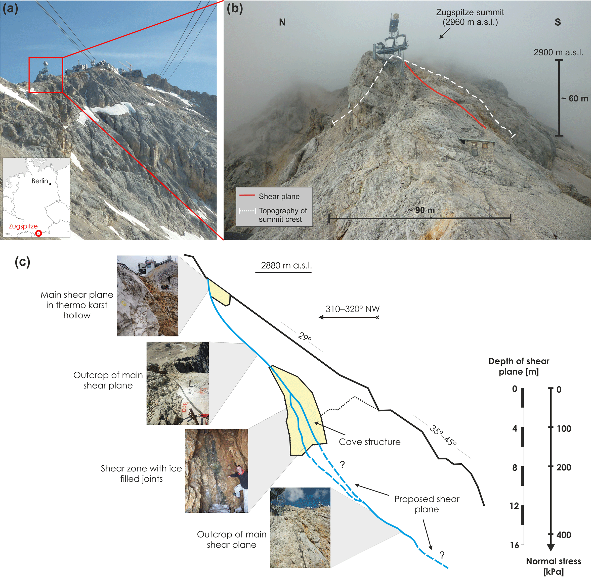
Figure 1(a) The Zugspitze summit area with Germany's highest peak (2962 m a.s.l.). (b) Profile view of the Zugspitze summit crest with dimensions of the rockslide. The supposed shear plane is indicated by the red line. (c) Mechanical situation and geometry of the ice-supported rockslide that is used as a real-world exemplification of the simulated temperature and stress-controlled fracturing along rock–ice interfaces in the laboratory.
In this study, we performed 141 shear tests, using limestone–ice–limestone samples with realistic ISRM (International Society for Rock Mechanics and Rock Engineering) rock surface roughness and predefined strain rates provoking fracturing. The onset of fracturing was controlled using the AE technique. To simulate the real-world fracturing of ice and rock–ice contacts along discontinuities in alpine permafrost rock slopes, our tests were performed in a temperature-controlled, cooled laboratory shear box with samples collected in the field. Our experiments focus on the impact of temperature and normal stress on the fracturing behaviour. Temperatures between −10 and −0.5 ∘C were tested to represent recently observed daily and annual mean temperatures of mountain bedrock permafrost (Böckli et al., 2011; Delaloye et al., 2016). Normal stresses of 100, 200 and 400 kPa (corresponding to rock overburdens of approximately 4, 8 and 15 m or more) were chosen to reconstruct relevant stress conditions for ice- and rock–ice fracturing processes in permafrost rock joints mostly below the annual maximum thaw depth. Additional tests at 800 kPa (i.e. 30 m rock overburden) were performed to study a potential stress-dependent transition from brittle fracture to creep at stress levels above 400 kPa.
This paper addresses the following questions:
-
How does the shear strength of ice-filled rock joints respond to permafrost warming (−10 to −0.5 ∘C) and sudden changes in rock–ice overburden (i.e. normal stress)?
-
Can we derive a comprehensive stress- and temperature-dependent failure criterion for ice-filled rock joints?
-
Which real-world conditions of permafrost rock slope destabilisation can be simulated by the new failure criterion?
-
Can AE be applied to decipher precursors of breaking ice and rock–ice interfaces within fractures?
2.1 Real-world setting to constrain laboratory tests
The design of the presented laboratory test set-up is inspired by a benchmark example of shallow, ice-supported rock instability prior to failure exemplified by an approximately 104 m3 large rockslide at the summit crest line (2885 m a.s.l.) of Germany's highest peak, the Zugspitze (2962 m a.s.l.; Fig. 1a and b). Since 2007, the rock mass creeps slowly at an average of 3.75 mm yr−1. From July to October it moves more than 5 times faster than in the remaining months.
The ice-supported rockslide acts as a real-world exemplification of the simulated temperature and stress-controlled fracturing along rock–ice interfaces in our laboratory, and as such, it is a benchmark analogue to constrain temperature and stress conditions for the performed tests.
- i.
The depth of the main shear plane is assessed to a maximum of 10–15 m due to field mapping. The corresponding normal stresses on this shear plane (mostly ≤400 kPa) lie within the range of the tested stress levels (Fig. 1c).
- ii.
The occurrence of permafrost is confirmed by permanent ice-filled caves and fractures along the main shear zone (Fig. 1c).
- iii.
The Zugspitze summit area is located at the lower permafrost extension limit. Current borehole temperatures at the peak of the Zugspitze average −1.3 ∘C within the permafrost core area (approximately 24 m away from the south face and 21 m away from the north face) and approach minima of −6 ∘C at the margins (ca. 5 m away from the north face) (Böckli et al., 2011; Gallemann et al., 2017; Krautblatter et al., 2010; Nötzli et al., 2010). These temperatures lie well within the range of the tested temperature levels in this study.
- iv.
A climatic warming in the last century and an even stronger temperature increase since the late 1980s can be observed at the Zugspitze, i.e. the mean annual air temperature (MAAT) in 1991–2007 was 0.8–1.1 ∘C warmer than in the three prior 30-year reference periods between 1901 and 1990 (Gallemann et al., 2017; Krautblatter et al., 2010). An ongoing warming may potentially cause the degradation of permafrost in the summit crest, leading to an accelerated movement in the future and thus to the fracturing of ice and rock–ice contacts, among other processes.
2.2 Sample preparation
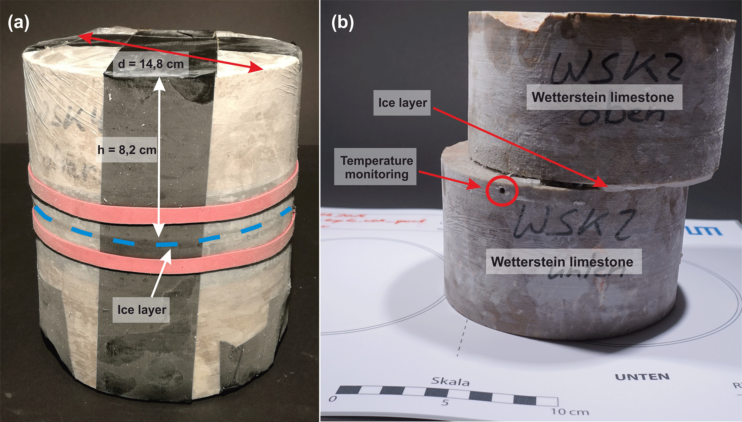
The tested rock samples were collected at the Zugspitze summit crest (Fig. 1a). The rock samples consist of Triassic Wetterstein limestone, which builds up the upper part of the Zugspitze (Jerz and Poschinger, 1995). The limestone is finely grained, dolomised, has a porosity of approximately 4.4 % and shows little heterogeneity in terms of its lithological properties (Krautblatter et al., 2010). Seven pairs of rock cylinders with a diameter of 148±1 mm and a height of 82±3 mm were prepared. Following the ISRM recommendations for standardised tests (Coulson, 1970; Ulusay, 2015), the roughness of the specimen's surfaces was produced using abrasive grinding powder with a grit of 80 grains per inch (FEPA, Federation of European Producers of Abrasives Standard), leading to a roughness amplitude equivalent to the mean diameter of the abrasive grains of 0.185 mm. Consequently, the rock surfaces are reproducible and close to the conditions of fractures in the field. The uniform joint surface roughness prohibits any potential effect on the shear strength results. Rock cylinders were saturated in a water bath under atmospheric pressure for at least 72 h.
The rock–ice–rock sandwich samples were produced by freezing two cylinders of Wetterstein limestone with a gap filled with tap water, using matchsticks as spacers. The samples were subjected to a number of pretests to guarantee uniform conditions. Pretests showed that simultaneous freezing of the interlocking rock surface and the ice surface is necessary to generate a firm contact. The gap was wrapped with tape and transparent film to prevent water draining (Fig. 2a). The 3±1 mm thin ice layer resembles the thin nature of most encountered infillings and provokes fracturing, as thicker ice infill produces more creep, camouflaging the fracturing behaviour. Our experiments (including the pretests) have shown that unavoidable thickness variations of ±1 mm yield no significant differences in fracture toughness (Fig. S1a in the Supplement). In other shear tests with constant stress, the shear strength of sandwich samples with a 1 mm thick ice layer also did not differ significantly from the results of concrete–ice specimens representing a 25 mm thick ice infilling (Günzel, 2008). All samples were frozen for at least 14 h at −14 ∘C to ensure that the ice layer was entirely frozen and firmly attached to the rock surfaces. During the freezing process, the shear planes and the gap for the ice layer were oriented vertically to make sure that no air bubbles could form in the ice. A hole was drilled into the lower rock cylinder (Fig. 2b) to monitor the rock temperature during the shear test with a 0.03 ∘C precision Pt100 sensor (Greisinger GMH 3750).
2.3 Experimental set-up
After freezing, the sandwich specimens were fixed within the upper and lower ring of the RDS-100 direct rock shear machine from GCTS (Geotechnical Consulting & Testing Systems; Fig. 3a). The ice layer position then corresponded to the open gap between the upper and the lower shear ring (Fig. 3b). Consequently, failure within the ice layer or along the ice–rock interface is provoked. During the whole test series, we did not change the constellation of specimen pairs and always placed them identically oriented into the shear frame to prevent effects of variations in the surfaces of the shear planes.

Figure 3Experimental set-up showing the laboratory shear machine, acoustic emission monitoring system, the cooling device and the cooling box. RS: rock sample. T: rock temperature sensor.
The machine is embedded in an isolated box in which temperature can be held constantly at a specified level between −10 and −0.5 ∘C by a custom-designed FRYKA cooling device. The cooling operation is controlled by a Pt100 sensor placed inside the rock sample (Fig. 3b). The experiments were performed at temperatures of −0.5, −1, −2, −3, −4, −5, −6, −8 and −10 ∘C. Ventilation prevented thermal layering inside the cooling box. An AE monitoring system with two sensors was fixed at the top of the upper specimen ring (Fig. 3b) to record the elastic waves generated during fracturing events. Due to the external hydraulic control, AE can be better recorded than in servo-controlled devices.
The hydraulically driven normal load and shear velocity were adjusted by the rock shear machine and were held at constant levels during the shear tests. Normal stress levels of 100, 200 and 400 kPa were applied for the whole temperature range. Tests at 800 kPa were performed to study a potential gradual stress-dependent transition from brittle fracture to creep. This transition is observed with increasing confining pressure in triaxial tests (Sanderson, 1988) and with increasing normal stress in uniaxial shear tests (Günzel, 2008) and is expected under the similarly tested normal stress conditions above 400 kPa. High rock overburden (i.e. 800 kPa) was simulated for temperatures from −4 to −0.5 ∘C, representing most of the recently measured annual mean temperatures of alpine and Arctic bedrock permafrost (Delaloye et al., 2016; Gallemann et al., 2017; Harris et al., 2003). In steep rock faces shear planes are inclined rather than horizontal. With increasing inclination of a shear plane at a certain depth, the normal stress acting on it will decrease and downhill forces will increase. Correspondingly, a shear plane with a normal stress of 200 kPa but a dip >0∘ will also exist in depths greater than 4 m. The mean horizontal displacement rate was 0.7±0.1 mm min−1, corresponding to a mean strain rate of s−1. The minimum test strain rate was s−1, which combines the minimum accounted deformation speed (0.005 mm s−1) and the maximum ice layer thickness of 4 mm. The shear rate was hereby calculated as the shear velocity (mm s−1) divided by the height of the ice layer (mm). This strain rate guaranteed the dominant deformation mode to be ice fracturing instead of creep, as 10−3 s−1 is the strain rate threshold for ice fracturing (Arenson and Springman, 2005a; Sanderson, 1988). As the shear and compressive strength of pure and dirty ice increases with the strain rate (Arenson et al., 2007; Sanderson, 1988; Schulson and Duval, 2009; Yasufuku et al., 2003), variations in the shear rate were kept as low as possible (with ±0.1 mm min−1) and had no measurable influence on the shear strength at failure (Fig. S1b). These conditions were applied to all tested stress and temperature conditions.
During the shear tests, normal load, shear load, normal deformation and shear deformation were recorded and used to calculate normal and shear stress considering the changing area of contact Acontact (Fig. S2):
with specimen radius r (mm) and shear displacement Δx (mm).
Between one and six experiments were performed for each test condition characterised by a specific temperature and normal stress level (Table S1 in the Supplement). The total number of tests was 141, significantly more than the cumulative number of the tests in all previously published studies on rock–ice failure.
2.4 Developing a temperature-dependent failure criterion for ice-filled rock joints
To develop a shear strength description of ice-filled permafrost rock joints we used the linear and stress-dependent Mohr–Coulomb failure criterion (a combination of Coulomb, 1773, and Mohr, 1900; a discussion of its limitations is given in Jaeger et al., 2007):
which represents the shear stress at failure τ as a function of the normal stress σ, the cohesion c and the friction angle φ. The Mohr–Coulomb failure criterion has not only been suggested for rock mechanics but also for ice mechanics (Arenson and Springman, 2005b; Sanderson, 1988). Using this failure criterion is essential to include ice mechanics and rock mechanics in the same model.
The linear envelopes for the friction and the cohesion (as functions of the temperature) were quantified based on the shear stress as failure dependent on normal stress. The cohesion values were derived by taking the shear stress values at the intercepts of the regression lines with the abscissas for each tested temperature level. The friction values were determined by taking the slope values from the linear regression functions, which correspond to the coefficient of friction μ. Values for the friction angle were derived by calculating the respective arc tangents of μ. The cohesion and the friction of ice-filled rock joints as a function of temperature were calculated by linear fitting, which is estimated by a linear regression model using the LinearModel class of MATLAB (Version R2017a). The predictor and response variables are arithmetic means, while only the predictor variable is weighted with the reciprocal value of its variance. In addition to the correlation coefficient (r) and the coefficient of determination (R2), the MATLAB function returns the regression parameters “intercept” and “slope” with its standard error (MathWorks, 2017).
The equations for the cohesion and the friction were combined to a new shear strength description for ice-filled rock joints based on Mohr–Coulomb. A validation test was performed at the end comparing the measured peak shear stresses with the model and its uncertainties at each tested temperature level.
2.5 AE monitoring
For measuring the acoustic activity, a two-channel high-frequency acquisition system composed of two USB AE nodes (Mistras, Physical Acoustics) employing a single-channel AE digital signal processor with 16-bit resolution and 10 V maximum amplitude was used. The AE sensors were coupled to the specimen holder using silicone-free lubricating grease (Glisseal HV, Borer Chemie). The AE piezoelectrical sensors (PK6I) provided an operating frequency range of 40–70 kHz with a resonant frequency of 55 kHz. They included a preamplifier of 26 dB and were connected to the USB AE node with coaxial cables. The system was controlled by AEwin (Mistras, Physical Acoustics), a real-time data acquisition software. The system sampled continuously with 1 MSPS (mega samples per second), while events over a fixed threshold of 70 dB were recorded. The signal characteristics (timestamp, rise time, amplitude, pulse count, energy and length) were parameterised according to Girard et al. (2012, Fig. 1).
3.1 Typical behaviour of shear stress, shear deformation and acoustic signals
A representative time series for shear stress, shear deformation and AE activity is shown in Fig. 4. A selection of additional time series is displayed in Fig. S3.
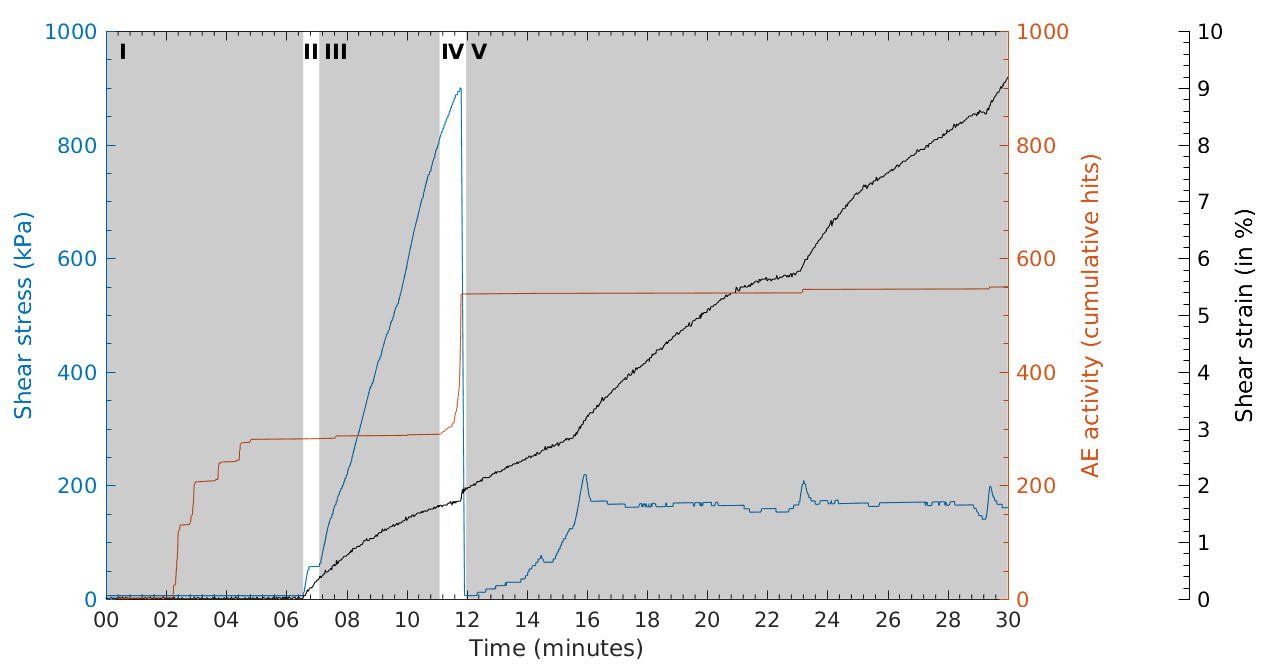
Figure 4Typical curves of shear stress, shear strain and acoustic activity for a shear test at ∘C and normal stress σ=200 kPa. Stages (I)–(V) represent the typical stages of each experiment: consolidation (I), sample fitting to shear rings (II), pre-peak shear deformation (III), shear failure (IV) and post-peak shear strength (V). Rupture is clearly detectable by the strong decrease in shear stress. An increase in the evolution of the cumulative AE hits can be observed before rupture.
In Stage I, the experiment starts with a consolidation of approximately 5–6 min applying the specified normal load. After initial AE activity during initial consolidation (starting after 2–3 min, Fig. 4), the AE hit rate decreases again to almost zero (after 5 min, Fig. 4) before entering Stage II. Shearing starts, and the shear rings gain a tight fit to the sample and then start to apply the stress. In Stage III, shear stress increases without significant changes in AE hit rate corresponding to elastic and ductile ice deformation. In Stage IV, a pronounced peak shear stress is observed in all experiments after a few minutes coinciding to a pronounced rise in the AE hit rate that indicates brittle failure. Correspondingly, the ice infill between the rock cylinders fails and shear deformation reaches one of its maximum values. The moment of failure can also be identified by a clearly audible cracking. In Stage V, just after failure, the shear stress suddenly drops to a minimum, then rises again and quickly reaches a plateau of residual shear stress. In a few experiments (such as in Fig. 4), the post-failure shear stress exhibits several small peaks, which are often accompanied by a minor increase in AE hits, audible cracking and a pronounced rise in shear strain. The peaks in shear stress may refer to healed ice that breaks when stresses exceed a certain threshold. Further, more than 90 % of the samples with observed post-failure peaks also failed within the ice or both in the ice and along the rock–ice interface. Hence, these peaks may also be caused by ice–ice interlocking, leading to the observed decrease in shear strain (Fig. 4). Subsequent failure occurs when the shear stresses overcome the ice strength.
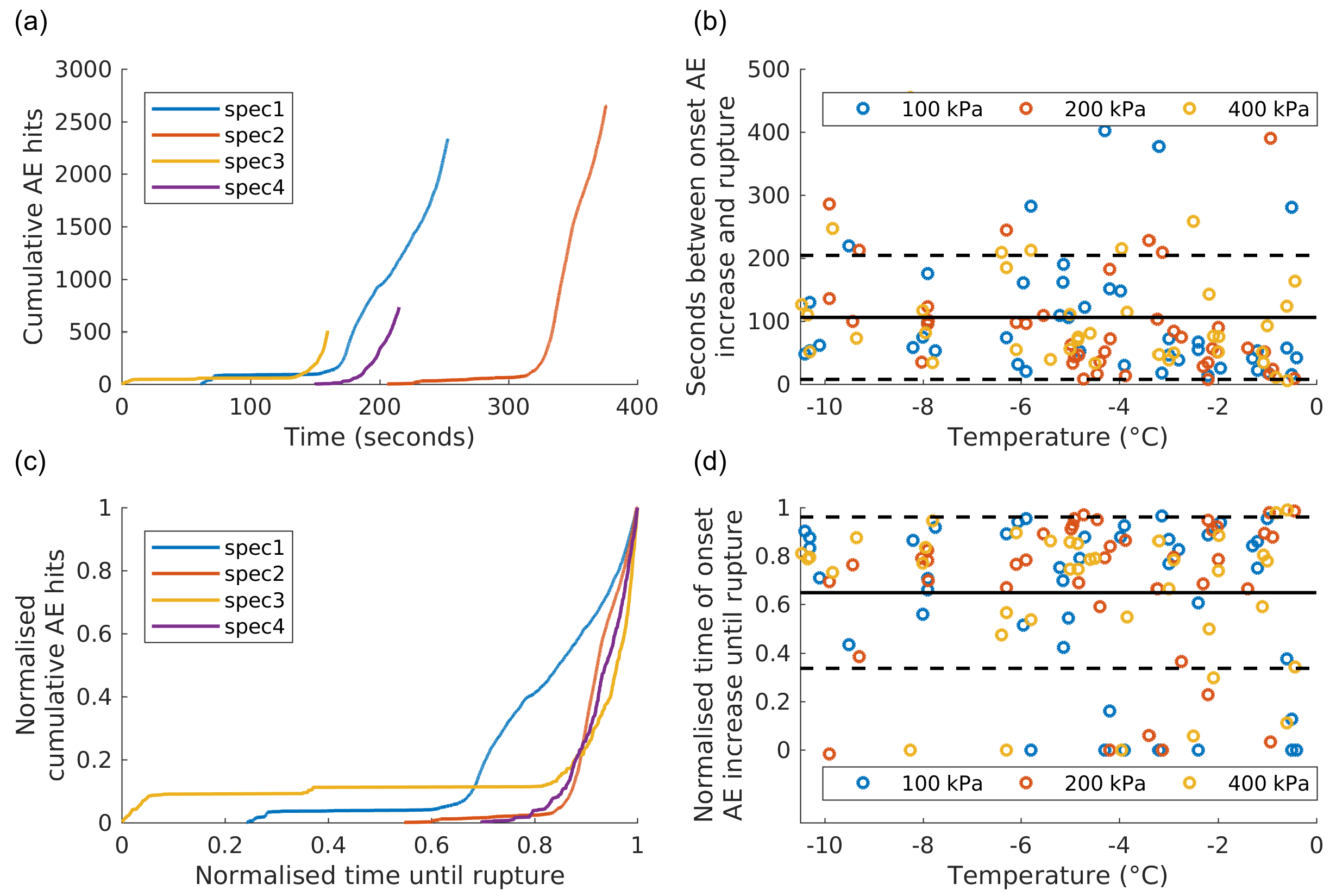
Figure 5Time series of (a) cumulative AE hits and (c) normalised cumulative AE hits with 400 kPa normal stress and at −4 ∘C. Time zero corresponds to the shear start of the experiments (spec1–4). Curves starting at x>0 represent tests in which the first AE signals were recorded a certain time after shear start. The temperature-dependent time between onset of AE increase and rupture is displayed in seconds (b) and normalised (d). The black lines indicate the overall mean while the dashed lines indicate the standard deviation range. Tests at 800 kPa were not considered in (b) and (d) because they were only conducted at temperatures between −0.5 and −4 ∘C.
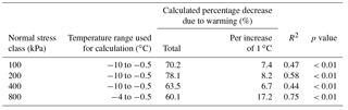
Table 1Calculated decrease in shear stress at failure with increasing temperature.
The number of AE hits usually increases very suddenly and sharply just before failure (Fig. 5a and c). The average offset between the onset of AE hit increase and fracturing (i.e. Stage IV) is 107±98 s (Fig. 5b). In all the experiments, the onset of AE hit increase occurs when 65±31 % (mean value with standard deviation) of the time between shear start and failure has passed (Fig. 5d). However, in some experiments at temperatures between −4 and −0.5 ∘C, the AE hit increase starts even earlier than within the standard deviation of 31 % (outliers <34 %). The lag in absolute and relative time shows a weak correlation to temperature, though it is not dependent on normal stress.
To analyse the scaling properties of the AE energy, we calculated the distribution for each experiment condition, combining the data of all experiments with the same condition to enlarge the number of events. The probability density functions (PDFs) of event energy show a power-law behaviour spanning 3–5 orders of magnitude (Fig. S4). The exponent b is between 1.6 and 1.9 for the different conditions, but it does not show any relation to temperature or normal load. As a result, it does not indicate any stress or temperature dependence of the size of fracturing events.
3.2 Shear stress at failure and its temperature dependence
The shear stress at failure decreases with increasing temperature at all tested normal stress levels (Fig. S5). Table 1 shows the decrease in shear stress at failure with increasing temperature for each tested normal stress condition. The calculated total decrease at stresses 100–400 kPa ranges between 63.5 % and 78.1 % and refers to a warming from −10 to −0.5 ∘C. The maximum decrease at 800 kPa measures 60.1 % and refers to temperatures from −4 to −0.5 ∘C.
3.3 Developing a temperature-controlled brittle failure criterion for ice-filled permafrost rock joints
Shear stress at failure versus normal stress was plotted for all temperature levels and normal stresses from 100 to 400 kPa (blue regression lines; Fig. 6) and additionally for temperatures from −4 to −0.5 ∘C and normal stresses from 100 to 800 kPa (orange regression lines; Fig. 6). Here, the peak shear stresses generally increase with increasing normal stresses at all tested temperatures.
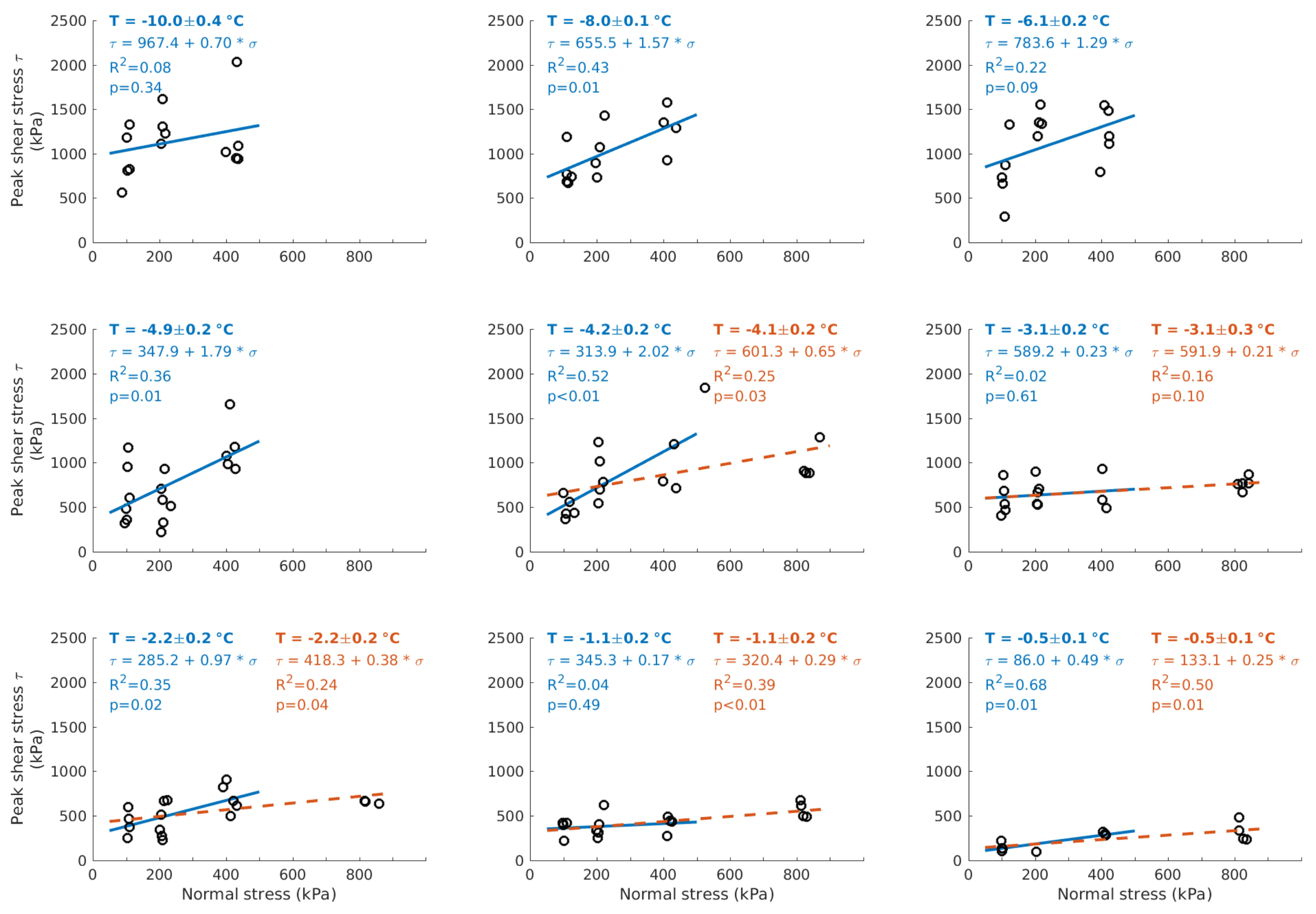
Figure 6Measured shear stress at failure as a function of normal stress for temperatures between −10 and −0.5 ∘C. The temperature values are the means (including standard deviation) of the measured rock sample temperatures (close to the moment of failure) of all experiments belonging to a specific temperature level. Normal stress levels of 100, 200 and 400 kPa were applied for the whole temperature range. The level of 800 kPa was additionally tested between −4 and −0.5 ∘C. Blue solid lines: calculated regression lines for normal stresses at 100–400 kPa. Orange dashed lines: calculated regression lines for 100–800 kPa. p: probability of rejecting the null hypothesis (H0) although it is true.
We utilised Fig. 6 to calculate the linear envelopes of cohesion and friction as functions of the temperature (Sect. 2.4). A temperature-dependent cohesion and friction for all test temperatures is displayed in Fig. S8. Here, R2 values range between 0.61 and 0.92 for the cohesion and between 0.12 and 0.40 for the coefficient of friction. P values measure <12 % for the cohesion and 7 %–57 % for the coefficient of friction. The ranges depend on the included stress levels and the temperature range tested. Due to these high uncertainties, we used only specific temperature levels with a statistical significance level of p≤5 % for the elaboration of the Mohr–Coulomb failure criterion. The p values had been calculated earlier for the relation between peak shear stress and normal stress at the tested temperature levels (Fig. 6). The temperature levels with p values > 5 % were excluded from further steps of the model development, as the corresponding peak shear stresses are considered to be not significantly dependent on the normal stress. Further, only the shear experiments from 100 to 400 kPa were utilised for the development of the failure criterion, as they cover the whole range of tested temperatures. This leads to a greater valid temperature range for the model and to a more robust correlation between cohesion or friction and temperature.
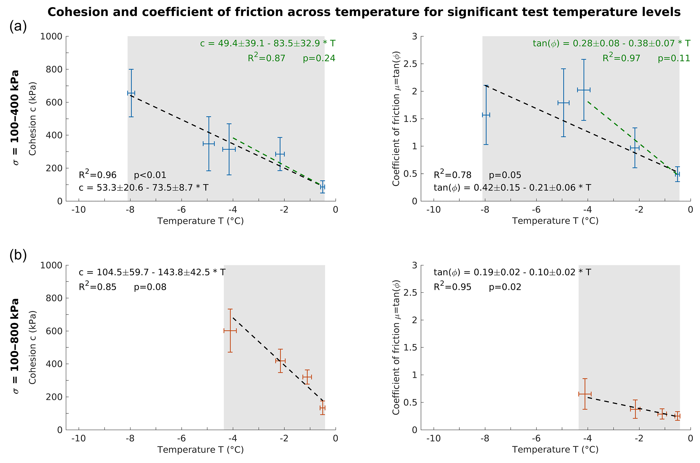
Figure 7Cohesion and friction of ice-filled rock joints as a function of temperature for significant temperature levels with a statistical significance level of p≤5 %. The crosses display the means and standard deviations of rock temperature and cohesion or friction, grouped by the tested temperature classes. (a) Tests at normal stresses at 100–400 kPa and temperatures at −8 to −0.5 ∘C (blue crosses). (b) Tests at normal stresses at 100–800 kPa and temperatures at −4 to −0.5 ∘C (orange crosses). The dashed lines represent the linear regression functions, which were inversely weighted with the squared standard errors. The green regression lines in (a) refer to a temperature range from −4 to −0.5 ∘C. The grey areas represent the valid temperature range for the respective parameter.
Figure 7 shows the temperature-dependent cohesion and friction of ice-filled rock joints for temperature levels with p≤5 % (Fig. 6). Here, the temperature-dependent loss of cohesion of ice-filled rock joints is described by
where T (∘C) is the temperature of the ice-filled joint at failure, valid for temperatures from to ∘C and normal stresses from 100 to 400 kPa (Fig. 7a).
When approaching the melting point, the cohesion decreases by 86 % from −8 to −0.5 ∘C (Table 2). Equation (4) exhibits a decrease in cohesion of 74 kPa ∘C−1 due to warming, which refers to a reduction by 12 % ∘C−1. The temperature-dependent friction coefficient can be expressed by
where T (∘C) is the temperature of the ice-filled fracture at failure, valid for temperatures between and ∘C and normal stresses from 100 to 400 kPa (Fig. 7a). The coefficient of friction falls by 75 % with increasing temperature from −8 to −0.5 ∘C (Table 2). The corresponding friction angle decreases by 60 % (64.5–27.7∘). This equation shows a warming-dependent loss of friction of 0.21 ∘C−1 corresponding to a reduction by 10 % ∘C−1.
We did not perform tests at temperatures warmer than −0.5 ∘C because we assume the ice to melt or be squeezed out of the rock cylinders, which leads to shearing along rock–rock contacts. Cohesion will be absent at the melting point and shear strength values will rise. This is shown by the tests of Davies et al. (2001) in which the shear strengths of ice–concrete samples closely approach the concrete–concrete sample line.
Combining Eqs. (4) and (5) in a Mohr–Coulomb failure criterion (Eq. 3), we can describe a temperature-dependent and normal stress-dependent shear stress at failure τ (kPa) for ice-filled rock joints:
where the friction angle is the arc tangent of μ while both friction and cohesion respond to a temperature increase. This formula is valid for normal stresses between 100 and 400 kPa and temperatures between and ∘C.
3.4 Cohesion and friction for normal stresses between 100 and 800 kPa
When comparing the loss of friction and cohesion for normal stresses 100–400 kPa with the loss for 100–800 kPa, both in the same temperature range of −4 and −0.5 ∘C, the following can be observed (Fig. 7, Table 2): (i) the absolute reduction in cohesion is more pronounced for tests including all normal stress levels; (ii) the absolute decrease in friction is stronger for tests excluding 800 kPa and (iii) percentage decreases are nearly the same for both groups of tests.
3.5 Failure type and its dependence on temperature and normal stress
Three types of failure could be observed during the shearing tests: (i) fracture along the rock–ice interfaces (Fig. S7a), (ii) fracture within the ice layer and (iii) a composite fracture type of (i) and (ii) (Fig. S7b). In the first type, the entire ice infill stuck to either the upper or the lower rock cylinder, whereas in the second case the rock surfaces were unaffected by failure. The last fracture type refers to specimens whose ice layer broke transversely and was separated so that the rear portion remained at the lower cylinder and the front part stuck to the upper one.
Table 2Calculated absolute and percentage decrease in cohesion and friction due to warming for various normal stress and temperature ranges.
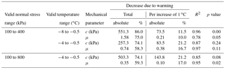
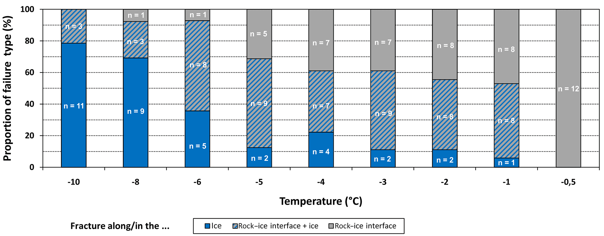
Figure 8Proportions and absolute numbers of fracture types plotted at temperatures from −10 to −0.5 ∘C (for tests at 100–800 kPa). Failures inside the ice dominate at low temperatures whereas failure along rock–ice interfaces become more important close to 0 ∘C.
With temperatures rising from −8 to −0.5 ∘C, the percentage of tests with fracture along the rock–ice interface increase from 8 % to 100 % (Fig. 8). At −0.5 ∘C it constitutes the only failure type. However, the lower number of tests at this temperature level has to be considered. Vice versa, the proportion of fracturing within the ice infillings increases with decreasing temperature from 6 % at −1 ∘C to 79 % at −10 ∘C. At −8 and −10 ∘C, it is the dominating failure type. The composite failure type shows no clear trend, with either decreasing or with increasing temperature. A clear relationship between failure type and normal stress could not be identified (Fig. S8).
Our experimental results generally show decreasing shear strength of ice-filled rock joints with increasing temperature and decreasing normal stress. We used these data to develop a new brittle failure criterion for ice-filled permafrost rock joints (Eq. 6), which is based on Mohr–Coulomb and shows that both the cohesion and the friction are temperature dependent and decrease with increasing temperature (R2=0.96 for the cohesion and R2=0.78 for the friction). Similar tendencies have been indicated by previous studies of the shear strength of ice-filled rock joints (Davies et al., 2000, 2001; Günzel, 2008; Krautblatter et al., 2013). However, all of these studies were performed with a much smaller number of experiments and with concrete as a rock analogue; further, their results have not yet been combined into a comprehensive failure criterion.
4.1 Real-world conditions of permafrost rock slope destabilisation simulated by the new failure criterion
The experiments presented apply to real-world rock–ice fracturing in rock slope failures (i) with ice-filled failure planes in a depth of 4 to 15 m, i.e. mainly below the active layer and shallower than the ice fracturing suppression in favour of creep deformation of ice, (ii) with virtually all realistic alpine and Arctic permafrost bedrock temperatures between −0.5 and −10 ∘C, and (iii) with fast displacements (0.7±0.1 mm min−1) coinciding with the final accelerating failure stage. Rock–ice fracturing certainly dominates rock failure volumes of m3 in which all ice-filled failure planes are ≤15 m deep (Sect. 1), but it might also play an important role for larger failures, for which just a certain proportion of ice-filled failure planes are ≤15 m deep.
If we leave the range of considered boundary conditions in terms of (i) higher normal stresses, (ii) lower temperatures or (iii) lower strain rates, fracturing along ice-filled permafrost rock joints will presumably not occur. (i) A potential gradual stress-dependent transition from brittle fracture to creep is expected at the tested normal stresses above 400 kPa. In our experiments, all sandwich shear samples, including those at 800 kPa normal stress, only failed by fracturing, presumably due to the elevated strain rate of 10−3 s−1, leading to fracture. It appears that the transition from shear fracturing to creep is not only stress dependent but also strain rate dependent within a certain transition level of normal stress (Sanderson, 1988). Other reasons for the unexceptional fracture-dominated failures are that the simulated rock overburden of 30 m may still be within the transition depth and seems to favour fracturing at elevated strain rates. (ii) Tests at temperatures below −10 ∘C were not performed because measured daily and annual mean temperatures at various alpine and Arctic permafrost bedrock sites do not drop below −10 ∘C at depth (Böckli et al., 2011; Delaloye et al., 2016; Harris et al., 2003). (iii) The samples were sheared with high strain rates of 10−3 s−1 to provoke brittle failure of ice and rock–ice contacts. At lower strain rates, stress concentrations along the shear zone can be relaxed and the mechanical behaviour changes to ductile creep deformation without fracturing (Arenson and Springman, 2005a; Arenson et al., 2007; Krautblatter et al., 2013; Renshaw and Schulson, 2001; Sanderson, 1988).
Our experiments simulate the final accelerating stage of rock slope failure in which the structure of the ice infillings is deformed by intense shear displacement. The ice infill at the start of the shear tests reproduces an ice-filled joint that has already been loaded and deformed by uniaxial compression. This is somehow similar to polycrystalline ice in natural fractures as ice has a high capacity to perform self-healing and thus deletes previous deformation-induced imperfections. At strain relaxation, the ice bonding heals itself within hours and days due to refreezing and causes a strengthening of the sample (Arenson and Springman, 2005a; Sanderson, 1988); thus a sample with a preset normal stress is similar to an ice-filled fracture under similar conditions irrespective of the deformation history. In this study, the bonding of the rock–ice interface is mostly established by adhesion, whereas rock–ice interlocking is less important due to the small surface roughness of the rock samples.
So far the failure of ice-filled permafrost rock joints has been studied using concrete as a rock analogue (Davies et al., 2000; Günzel, 2008). For the first time, we use rock to closely reproduce real conditions along rock joints. Synthetic materials possibly deviate from shear strength values representative for rock joints in the field. For instance, ice sliding on granite shows a friction coefficient μ approximately 3–4 times higher than ice sliding on glass or metals, all having a similar surface asperity roughness. The higher friction of the granite–ice interfaces is due to a higher effective adhesion (Barnes et al., 1971). We assume that the shear strength of rock–ice interfaces is mostly affected by temperature, normal stress, strain rate and joint surface roughness. However, the applied constant strain rate as well as the standardised preparation of a uniform joint surface roughness prohibit any potential effects on the shear strength. We postulate that the influence of the rock type on the shear strength is less important for the following reasons:
- i.
The thermal conductivity of the rock may affect the shear strength by facilitated melting along heat-insulating surfaces, causing a decrease in friction (Barnes et al., 1971). The thermal conductivity of rocks varies in a range of 0.3–5.4 W m−1 K−1 (Clauser and Huenges, 1993; Schön, 2015). A metal like brass, with a much higher thermal conductivity of 100 W m−1 K−1, would lead to a warming at the interface 14.5 ∘C lower than granite (Barnes et al., 1971). Due to the relatively small range of thermal conductivities for different rock types, we do not expect a rock-type-dependent effect on the shear strength.
- ii.
The porosity of the rock and the type of constitutive minerals may play a role in the growth of ice crystals along the rock–ice interface, which in turn affects the shear strength. The strain rate and the compressive strength of ice crystals are significantly higher for those oriented parallel to the applied stress than for those oriented randomly (Hobbs, 1974; Paterson, 1994). However, we assume any potential rock-type-dependent orientations of ice crystals to be deleted before shearing starts due to the applied uniaxial compression during initial consolidation.
- iii.
The strength of the constitutive minerals of the rock surfaces may control the friction of the rock–ice contact. However, we assume the strength of minerals to play a minor role in the shear strength because at the rock–ice interface the ice will fail before the rock material and ice strength will control the failure process. In our tests we could not observe particles breaking off the rock surfaces. Elastic moduli of most rock minerals (bulk modulus k: 17–176 GPa; shear modulus μ: 9–95 GPa) are 2–20 times higher than those of ice (k: 8.9 GPa; μ: 3.5 GPa) (Schulson and Duval, 2009; Schön, 2015). The small applied roughness of the shear surfaces additionally prevented any relevant impact of differing mineral strengths.
- iv.
Rock minerals heat up differently and can generate thermal stresses (Gómez-Heras et al., 2006) in the intact rock and along discontinuities, causing thermal fatigue and a reduction in the shear resistance (Dräbing et al., 2017). However, we do not expect an impact on the shear strength as repetitive temperature cycles with high magnitude and frequency are required for thermal stress fatigue (Hall and Thorn, 2014). During our tests, temperatures were kept constant.
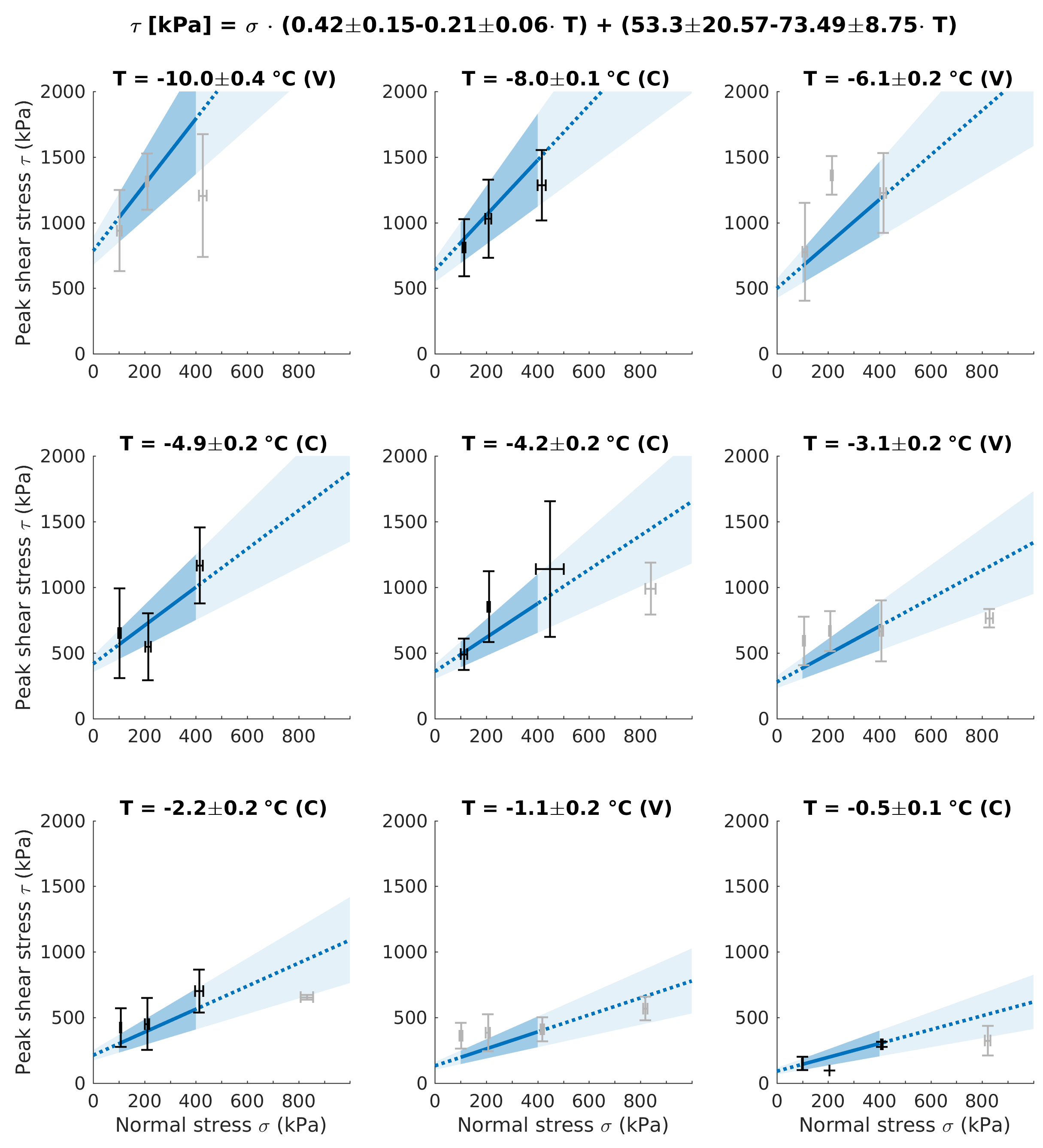
Figure 9Validation test for the new Mohr–Coulomb failure criterion for ice-filled rock joints (Eq. 6). The black and grey crosses represent means and standard deviations of normal stress and peak shear stress, grouped by the tested normal stress classes 100, 200, 400 and 800 kPa. C: calibration temperature level that was used for the model as p≤5 % (black crosses). V: validation temperature level that was excluded from the elaboration of the failure criterion because p>5 % (grey crosses). As tests at 800 kPa were excluded from the development of the failure criterion, they also serve as validation (grey crosses). Solid blue lines and dark blue areas represent the calculated failure criterion and respective error ranges within the valid normal stress range. Dotted blue lines and light blue areas are extrapolations of the failure criterion and error margins beyond the valid normal stress range.
Thus, the tests using limestone represent rock–ice fracturing along joints of all rock types. To use rock instead of other materials probably has a greater effect on the shear strength than different rock types. Still, a potential shear strength dependence on different rock types has to be proven in additional experiments. Further, it is certainly interesting to systematically analyse the strain-rate-dependent brittle fracture–creep transition beyond 800 kPa normal stress or the influence of the joint surface roughness on the shear strength and the failure behaviour in other studies, but this is beyond the scope of this study.
4.2 Validation of the new failure criterion
The new derived failure criterion (Eq. 6) describes the shear strength of ice-filled fractures in all types of rock and combines a temperature-dependent cohesion and friction angle. A temperature dependence of both the cohesion and friction angle has not been demonstrated yet, but for pure ice (Fish and Zaretzky, 1997). However, other publications have postulated either a temperature dependence of the cohesion of ice-rich soils (Arenson and Springman, 2005b; Arenson et al., 2007) or a temperature dependence of the friction coefficient of granite–ice interfaces (Barnes et al., 1971). Here, we have developed a failure criterion for rock–ice interfaces that contains both a temperature-dependent coefficient of friction and an even stronger temperature-dependent cohesion.

Figure 10Progressive failure in a warming permafrost rock slope displaying thermal and normal stress conditions before and after detachment of a first slab. Both can initiate failure: (B2) progressive thermal warming (i.e. permafrost degradation) occurs within years, but (B1) sudden unloading develops even faster within days.
Figure 9 depicts the new Mohr–Coulomb failure criterion (Eq. 6) with the range of uncertainty for the different temperature levels tested and corrected by their true means (including standard deviation). The means of the measured peak shear stress values, represented by the intersections of the error bars of normal stress and peak shear stress, mostly correlate well with the calculated failure criterion and the respective error ranges. Statistical dispersion measures of the measured peak shear stress values around the failure criterion are shown in Table S2. Best accordance is achieved for the shear stress means used for model calibration (correspond to significant temperature levels with p values ≤ 5 %). The mean absolute deviation (MAD) and coefficient of variation (CV) range between 40 and 146 kPa and between 8.8 % and 24.6 % respectively. The experiments at temperatures −1, −3, −6 and −10 ∘C (with p values > 5 %), which had been excluded from the elaboration of the failure criterion, were used for validation. Their shear stress means show higher deviations from the failure criterion, i.e. the MAD and the CV range from 98 to 252 kPa and from 15 % to 43.5 % respectively. For normal stresses at 100–400 kPa, the model seems to show a robust fit even with values not included in the initial model development data set. The means of peak shear stress at 800 kPa mostly lie within the calculated error margins, but at their lower boundaries. This demonstrates the mechanical parameters controlling the failure behaviour start to change at higher normal stresses (800 kPa) and temperatures close to the melting point.
This study shows that both warming and unloading of ice-filled rock joints lead to a significant drop in shear resistance, which may cause a self-enforced rock slope failure propagation. The progressive degradation of bedrock permafrost and ice in rock joints may control the cohesion and friction angle of the joints. However, as soon as a first slab has detached from the rock slope (A in Fig. 10), further slabs below can become unstable and finally detach as the shear strength along the ice-filled failure plane is affected by progressive warming (i.e. permafrost degradation, B2 in Fig. 10), but even faster by sudden unloading (B1 in Fig. 10). The latter is represented by a significant drop in normal stress in the Mohr–Coulomb failure criterion (Fig. 11).
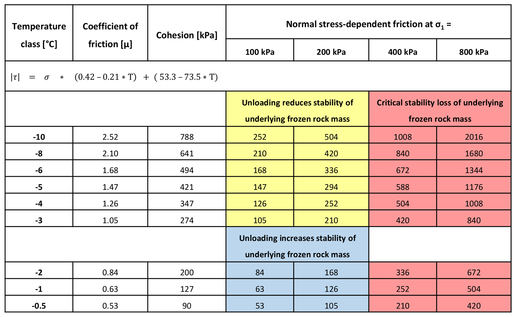
Figure 11Three scenarios of rock slope stability after the sudden unloading of an underlying frozen rock mass with 45∘ fractures. Blue boxes: increasing stability of underlying frozen rock mass. Unloading increases shear resistance relative to shear forces in 45∘ fractures. Yellow boxes: reducing stability. Unloading reduces shear resistance (friction) relative to shear stress in 45∘ fractures. Red boxes: critical stability loss. Friction loss along underlying 45∘ fractures even exceeds ice cohesion.
We consider three scenarios of rock slope stability depending on the reduction in normal stress and its relationship to cohesion along a specific shear plane with an inclination of 45∘. Correspondingly, all changes in shear forces equal the changes in the shear resistance Δτ=Δσ. However, instability may increase when the loss in friction surpasses the loss of applied shear forces: . This may happen in an underlying frozen rock mass upon unloading when μ or . The cohesion may possibly compensate for the decrease in friction when . In this case the shear plane could become more unstable without complete failure. This is valid for temperatures between −10 and −3 ∘C and normal stresses between 100 and 200 kPa (yellow boxes in Fig. 11). When the loss of friction in an underlying frozen rock mass upon unloading is much bigger than the reduction in the shear forces and even exceeds the ice cohesion , then failure along the shear plane is strongly promoted. This is valid for temperatures between −10 and −0.5 ∘C and normal stresses of 400–800 kPa (red boxes in Fig. 11). Rock slope stability in an underlying frozen rock mass upon unloading is only weakly affected if the reduction in friction is smaller than the reduction in the shear force: . This is valid for temperatures between −2 and −0.5 ∘C and normal stresses of 100–200 kPa (blue boxes in Fig. 11). In summary, the red scenario in Fig. 11 indicates a high likelihood of subsequent failures by unloading the underlying frozen rock mass, the yellow scenario exposes a moderate likelihood and the blue scenario shows a small likelihood. Unloading may lead to instability or even failure when the shear planes (i) are affected by a high reduction in normal stress exceeding the ice cohesion and/or (ii) are below −2 ∘C due to a friction coefficient higher than 1.
4.3 Cohesion and friction for normal stresses including 800 kPa
Combining the 100–400 kPa with the 800 kPa tests results in a higher (absolute) reduction of cohesion and a lower (absolute) loss in friction with increasing temperature (Fig. 7). The relatively low peak shear stress values at 800 kPa normal stress flatten the linear regression curves and raise their intercepts with the abscissas (Fig. 6). This behaviour can presumably be explained due to an enhanced pressure melting effect at higher normal stresses and temperatures close to 0 ∘C, leading to liquid formation along the rock–ice interface and decreasing the friction (see also Sect. 4.5; Arenson and Springman, 2005a; Barnes and Tabor, 1966; Hobbs, 1974). This hypothesis is supported by two findings. (i) Failures along the rock–ice contact dominate at higher temperatures between −0.5 and −5 ∘C (Fig. 8). (ii) The proportion of rock–ice failures to all failure types is 42 % for normal stresses at 100–400 kPa and temperatures from −0.5 to −4 ∘C. The corresponding proportion for the same temperature range and normal stresses at 100–800 kPa is 51 %. When tests at 800 kPa are added, the rock–ice failures in particular increase in number, whereas failures within the ice are not affected. At normal stresses of 800 kPa and temperatures below −4 ∘C, the enhanced pressure melting effect may reduce and shear stresses are expected to rise significantly.
4.4 AE activity as an indication of correlated damage, potentially preconditioning failure
AE is generally very capable of anticipating rock–ice failure as (i) all failures are predated by an AE hit increase, (ii) the hit rate increases well before brittle failure starts and (iii) AE peaks immediately prior to failure. This AE pattern coincides with observations in triaxial constant strain rate tests on frozen soil (Yamamoto and Springman, 2014). The experiments conducted clearly show that precursors before failure can be observed by the AE technique, providing complementary information to the displacement measurements. To exceed the AE trigger level, AE events have to be emitted from significantly large evolving microcracks and thus document microcrack generation and coalescence. It is interesting to consider that in ice, even secondary and tertiary creep are constituted by the generation and healing rate of microfractures (Paterson, 1994; Sanderson, 1988). The measured pre-failure increase in AE activity (Fig. S3) is thus an indication for damage increase, i.e. microcrack generation and coalescence typical for cryospheric damage propagation (Murton et al., 2016; Yamamoto and Springman, 2014). The culmination of progressive damage involves complex interaction between multiple defects and growing microcracks (Eberhardt et al., 1999; Senfaute et al., 2009; Sornette, 2006). An increase in the AE hit rate prior to failure accompanies the evolution of the internal damage and can therefore be used as a precursor signal.
The power-law distribution of the AE event energy, which shows only small variations for all different temperature and loading conditions, indicates that strength heterogeneity, a main factor influencing this parameter (Amitrano et al., 2012), is similar for all tests at different conditions. Hence, neither a stress nor a temperature dependence of the size of fracturing events is expected in the tested conditions. A main challenge with AE monitoring is the absolute comparison of the event number and energy. The measured signal is strongly influenced by the coupling of the sensor with the medium. Additionally, the event triggering depends on the selection of an amplitude threshold. However, relative comparison (e.g. evolution of the hit rate) and statistical means (e.g. exponent b) are not very sensitive to the above-mentioned challenges, as long as enough events are detected.
At temperatures above −4 ∘C, a higher number of samples displayed an earlier start in fracturing before failure occurred. This trend is visible in the higher number of outliers below the standard deviation range and at temperatures above −4 ∘C (Fig. 5d). It may be explained by the lower shear strength of samples at warmer temperatures. Accordingly, at colder temperatures failure is increasingly characterised by a later onset of AE events because of higher shear strengths. Challenges remaining for field application of the recorded offset between the onset of AE hit increase and shear failure are the positioning of the sensors and their density, the strength of the signal, and the missing signal emission history prior to instrumentation.
4.5 Failure types
Three types of failure were identified: fracture along the rock–ice interfaces, fracture within the ice layer and a composite type. From a practical point of view, Eq. (6) has to include all types of failure due to five main reasons:
- i.
We cannot observe what types occur in natural systems.
- ii.
A specific stress, strain or temperature condition could not be assigned explicitly to one of the failure types.
- iii.
Along spatially extensive rock joints, all these failure types coexist and coincide.
- iv.
All three types together fit in a failure criterion, showing that they converge to a range of values under given temperature and stress conditions.
- v.
It is physically impossible to constrain the exact fracturing plane in a sub-millimetre range away from the rock–ice interface.
In this study we observe a tendency of temperature dependence of the distinct failure types: when comparing fractures in the ice with fractures along the rock–ice contact, tests with the first failure type dominate at cold temperatures between −10 and −6 ∘C, while the proportion of tests with fracture along the rock–ice interface dominate at higher temperatures between −5 and −0.5 ∘C. This behaviour is similar to the pattern observed by Jellinek (1959), albeit at lower temperatures, showing “cohesive breaks” (comparable with fracture within the ice infilling) of ice–steel interfaces at temperatures colder than −13 ∘C and “adhesive breaks” (equal to fracture of rock–ice interfaces) at temperatures warmer than −13 ∘C. Previous publications highlight three potential reasons for this pattern that explain the formation of liquids, which may support the failure of rock–ice contacts at warmer conditions:
- i.
Above −3 ∘C the deformation of ice is increasingly influenced by pressure melting (Hobbs, 1974), which can be pronounced in regions of stress concentration along the shear plane (Arenson and Springman, 2005a; Arenson et al., 2007).
- ii.
In porous media, curvature-induced and interfacial pre-melting (caused by long-range intermolecular forces between different materials and phases) leads to a depressed equilibrium freezing temperature. An unfrozen liquid melt film, several nanometres thick, forms at the ice–solid interface at −1 ∘C, increasing its thickness when approaching 0 ∘C (Rempel et al., 2004).
- iii.
Grain boundary sliding occurs at temperatures above approximately −10 ∘C, which generates heat by friction (Hobbs, 1974) and may additionally support the formation of this liquid-like layer along the rock–ice interface.
Most of the documented failures in permafrost rock walls are likely triggered by the mechanical destabilisation of warming bedrock, discontinuities with rock bridges and joints with or without ice fillings. The latter may evolve into shear planes, supporting destabilisation on a larger spatial scale and leading to failure. To anticipate failure in a warming climate, we need to better understand how rock–ice mechanical processes affect rock slope destabilisation with temperatures increasing close to 0 ∘C.
This paper presents a systematic series of constant strain rate shear tests on sandwich-like limestone–ice–limestone samples (i) to simulate the brittle failure of ice infillings and rock–ice interfaces along ice-filled shear planes of rockslides, (ii) to study its dependence on temperature and normal stress and (iii) to develop a new brittle failure criterion for ice-filled permafrost rock joints. The set-up and boundary conditions of our experiments are inspired by a 104 m3, ice-supported rockslide at the Zugspitze summit crest. Our tests apply to failures of permafrost rock slopes (i) with volumes of m3, (ii) with ice-filled shear planes in a depth of 4–15 m, (iii) with bedrock temperatures between −0.5 and −10 ∘C and (iv) with high strain rates ( s−1) coinciding with the accelerating final failure stage. Tests at a rock overburden of 30 m and temperatures from −4 to −0.5 ∘C were performed to study a potential stress-dependent transition from brittle fracture to creep. Of all the previous laboratory studies on the shear strength of ice-filled joints, the data set presented is the most extensive, containing 141 tests at nine temperature and four normal stress levels. For the first time, preconditioned rock from a permafrost-affected rock slope was used.
Monitoring of AE activity during the shear tests was successfully used to describe the fracturing behaviour of rock–ice contacts focusing on the precursors of failure. The onset of AE hit increase occurred when 65 % of the time between shear start and failure had passed (107±98 s before failure). The shear strength clearly declines with decreasing normal stress and increasing temperature. At rock overburdens of 4 to 15 m, warming from −10 to −0.5 ∘C causes a decrease in shear strength by 64 % to 78 %. At a rock overburden of 30 m and warming from −4 to −0.5 ∘C, shear strength decreases by 60 %. Warming drastically reduces the shear resistance of ice-filled rock joints and is thus a key process contributing to permafrost rock slope failure. Progressive failure is initiated when a first slab has detached from a rock slope. The underlying frozen rock mass is subsequently destabilised by progressive thermal warming and even more quickly by sudden unloading. The latter may lead to instability or even failure when the shear planes (i) are affected by a high reduction in normal stress exceeding the ice cohesion and/or (ii) are below −2 ∘C due to a friction coefficient higher than 1.
For the first time, we have introduced a failure criterion for ice-filled permafrost rock joints that includes the fracturing of ice infillings, rock–ice interfaces and a combination of both. It is based on a Mohr–Coulomb failure criterion, it refers to joint surfaces which we assume similar for all rock types and it is valid for normal stresses at 100–400 kPa and temperatures from −8 to −0.5 ∘C. The failure criterion contains a temperature-dependent cohesion and coefficient of friction decreasing by 12 % ∘C−1 and by 10 % ∘C−1 respectively with increasing sub-zero temperatures. The model fits well to the measured calibration means and even to the values excluded from the model development, which mostly lie within or close to the calculated error margin. Further, we show that the failure type depends on the temperature and is also affected by higher normal stresses (i.e. 800 kPa) above −4 ∘C, which can presumably be explained by an enhanced pressure melting effect along the rock–ice interface.
The new failure criterion can be applied in numerical modelling and enables scientists and engineers to anticipate more accurately the destabilisation of degrading permafrost rock slopes, as it reproduces better real shear strength conditions along sliding planes.
All data concerning the tested samples, test conditions, time series of the shear experiments, acoustic emission and mechanical properties are available in the Supplement as *.xlsx or *.pdf files. The full data set is available upon request from the authors of the paper.
The supplement related to this article is available online at: https://doi.org/10.5194/tc-12-3333-2018-supplement.
PM, SW and MK designed the laboratory experiment. PM and SW prepared the experimental set-up as well as the rock samples. The experiment execution was supervised by PM, SW and MK. The tests were mainly carried out by TS. PM and SW performed the data analysis and prepared the paper, both with a substantial contribution from MK.
The authors declare that they have no conflict of interest.
The work was funded by the Technical University of Munich and Nano-Tera.ch
(ref. no. 530659). We acknowledge Maximilian Marcus Rau, who supported the
experiment execution in the context of his bachelor's thesis, and we thank
Christina Utz for her support in performing experiments in the course of her
student research project.
This work was
supported by the German Research
Foundation (DFG) and the
Technische Universität
München within the funding
programme
Open Access Publishing Fund.
Edited by: Christian Hauck
Reviewed by: Lukas
U. Arenson and Friederike Günzel
Alava, M. J., Nukala, P. K. V. V., and Zapperi, S.: Statistical model of fracture, Adv. Phys., 55, 349–476, https://doi.org/10.1080/00018730300741518, 2006.
Amitrano, D., Gruber, S., and Girard, L.: Evidence of frost-cracking inferred from acoustic emissions in a high-alpine rock-wall, Earth Planet. Sc. Lett., 341–344, 86–93, https://doi.org/10.1016/j.epsl.2012.06.014, 2012.
Arakawa, M. and Maeno, N.: Mechanical strength of polycrystalline ice under uniaxial compression, Cold Reg. Sci. Technol., 26, 215–229, 1997.
Arenson, L. U. and Springman, S. M.: Triaxial constant stress and constant strain rate tests on ice-rich permafrost samples, Can. Geotech. J., 42, 412–430, https://doi.org/10.1139/t04-111, 2005a.
Arenson, L. U. and Springman, S. M.: Mathematical descriptions for the behaviour of ice-rich frozen soils at temperatures close to 0 ∘C, Can. Geotech. J., 42, 431–442, https://doi.org/10.1139/t04-109, 2005b.
Arenson, L. U., Springman, S. M., and Sego, D. C.: The rheology of frozen soils, Appl. Rheol., 17, 12147, 1–14, https://doi.org/10.3933/ApplRheol-17-12147, 2007.
Baer, P., Huggel, C., McArdell, B. W., and Frank, F.: Changing debris flow activity after sudden sediment input: a case study from the Swiss Alps, Geology Today, 33, 216–223, https://doi.org/10.1111/gto.12211, 2017.
Barnes, P. and Tabor, D.: Plastic flow and pressure melting in the deformation of ice I, Nature, 210, 878–882, https://doi.org/10.1038/210878a0, 1966.
Barnes, P., Tabor, D., and Walker, J. C. F.: The friction and creep of polycrystalline ice, P. Roy. Soc. A-Math. Phy., 127–155, 1971.
Beniston, M., Farinotti, D., Stoffel, M., Andreassen, L. M., Coppola, E., Eckert, N., Fantini, A., Giacona, F., Hauck, C., Huss, M., Huwald, H., Lehning, M., López-Moreno, J.-I., Magnusson, J., Marty, C., Morán-Tejéda, E., Morin, S., Naaim, M., Provenzale, A., Rabatel, A., Six, D., Stötter, J., Strasser, U., Terzago, S., and Vincent, C.: The European mountain cryosphere: a review of its current state, trends, and future challenges, The Cryosphere, 12, 759–794, https://doi.org/10.5194/tc-12-759-2018, 2018.
Böckli, L., Nötzli, J., and Gruber, S.: PermaNET-BY: Untersuchung des Permafrosts in den Bayerischen Alpen, Teilprojekt PermaNET (EU Alpine Space Interreg IVb), Zürich, 60 pp., 2011.
Butkovich, T. R.: The ultimate strength of ice, SIPRE Res. Rep., 11, 12, 1954.
Clauser, C. and Huenges, E.: Thermal conductivity of rocks and minerals, in: Rock Physics & Phase Relations: A Handbook of Physical Constants, edited by: Ahrens, T. J., American Geophysical Union, Washington, D. C., 105–126, 1995.
Coulomb, C. A.: Essai sur une application des regles de maximis et minimis a quelques problemes de statique, relatifs a l'architecture, Mem. Math. Phys., 7, 343–382, 1773.
Coulson, J. H.: The effects of surface roughness on the shear strengths of joints, PhD thesis, University of Illinois, Urbana, Illinois, USA, 1970.
Cox, S. J. D. and Meredith, P. G.: Microcrack formation and material softening in rock measured by monitoring acoustic emissions, Int. J. Rock Mech. Min., 30, 11–24, https://doi.org/10.1016/0148-9062(93)90172-A, 1993.
Davies, M. C. R., Hamza, O., Lumsden, B. W., and Harris, C.: Laboratory measurement of the shear strength of ice-filled rock joints, Ann. Glaciol., 31, 463–467, https://doi.org/10.3189/172756400781819897, 2000.
Davies, M. C. R., Hamza, O., and Harris, C.: The effect of rise in mean annual temperature on the stability of rock slopes containing ice-filled discontinuities, Permafrost Periglac., 12, 137–144, https://doi.org/10.1002/ppp.378, 2001.
Delaloye, R., Hilbich, C., Lüthi, R., Nötzli, J., Phillips, M., and Staub, B.: Permafrost in Switzerland 2010/2011 to 2013/2014, Glaciological Report (Permafrost) No. 12–15, PERMOS, Cryospheric Commission of the Swiss Academy of Sciences, Fribourg, 85 pp., 2016.
Deline, P., Gruber, S., Delaloye, R., Fischer, L., Geertsema, M., Giardino, M., Hasler, A., Kirkbride, M., Krautblatter, M., Magnin, F., McColl, S., Ravanel, L., and Schoeneich, P.: Ice Loss and Slope Stability in High-Mountain Regions, in: Snow and Ice-Related Hazards, Risks and Disasters, edited by: Shroder, J. F., Haeberli, W., Whiteman, C., Academic Press, Boston, 521–561, 2015.
Draebing, D., Haberkorn, A., Krautblatter, M., Kenner, R., and Phillips, M.: Thermal and Mechanical Responses Resulting From Spatial and Temporal Snow Cover Variability in Permafrost Rock Slopes, Steintaelli, Swiss Alps, Permafrost Periglac., 28, 140–157, https://doi.org/10.1002/ppp.1921, 2017.
Dramis, F., Govi, M., Guglielmin, M., and Mortara, G.: Mountain permafrost and slope instability in the Italian Alps: The Val Pola Landslide, Permafrost Periglac., 6, 73–81, https://doi.org/10.1002/ppp.3430060108, 1995.
Dwivedi, R. D., Soni, A. K., Goel, R. K., and Dube, A. K.: Fracture toughness of rocks under sub-zero temperature conditions, Int. J. Rock Mech. Min., 37, 1267–1275, 2000.
Eberhardt, E., Stead, D., and Stimpson, B.: Quantifying progressive pre-peak brittle fracture damage in rock during uniaxial compression, Int. J. Rock Mech. Min., 36, 361–380, 1999.
Fellin, W.: Einführung in die Eis-, Schnee- und Lawinenmechanik, Springer Vieweg, Berlin, Heidelberg, 2013.
Fischer, L., Kääb, A., Huggel, C., and Nötzli, J.: Geology, glacier retreat and permafrost degradation as controlling factors of slope instabilities in a high-mountain rock wall: the Monte Rosa east face, Nat. Hazards Earth Syst. Sci., 6, 761–772, https://doi.org/10.5194/nhess-6-761-2006, 2006.
Fish, A. M. and Zaretzky, Y. K.: Ice strength as a function of hydrostatic pressure and temperature, in: CRREL Report, Cold Regions Research and Engineering Laboratory, 97, 1–13, 1997.
Gagnon, R. E. and Gammon, P. H.: Triaxial experiments on iceberg and glacier ice, J. Glaciol., 41, 528–540, 1995.
Gallemann, T., Haas, U., Teipel, U., von Poschinger, A., Wagner, B., Mahr, M., and Bäse, F.: Permafrost-Messstation am Zugspitzgipfel: Ergebnisse und Modellberechnungen, Geologica Bavarica, 115, 1–77, 2017.
Girard, L., Beutel, J., Gruber, S., Hunziker, J., Lim, R., and Weber, S.: A custom acoustic emission monitoring system for harsh environments: application to freezing-induced damage in alpine rock walls, Geosci. Instrum. Method. Data Syst., 1, 155–167, https://doi.org/10.5194/gi-1-155-2012, 2012.
Gischig, V. S., Moore, J. R., Keith, F. E., Amann, F., and Loew, S.: Thermomechanical forcing of deep rock slope deformation: 2. The Randa rock slope instability, J. Geophys. Res., 116, F04011, https://doi.org/10.1029/2011JF002007, 2011.
Glamheden, R. and Lindblom, U.: Thermal and mechanical behaviour or refrigerated caverns in hard rock, Tunn. Undergr. Sp. Tech., 17, 341–353, 2002.
Gobiet, A., Kotlarski, S., Beniston, M., Heinrich, G., Rajczak, J., and Stoffel, M.: 21st century climate change in the European Alps-A review, Sci. Total Environ., 493, 1138–1151, https://doi.org/10.1016/j.scitotenv.2013.07.050, 2014.
Gómez-Heras, M., Smith, B. J., and Fort, R.: Surface temperature differences between minerals in crystalline rocks. Implications for granular disaggregation of granites through thermal fatigue, Geomorphology, 78, 236–249, https://doi.org/10.1016/j.geomorph.2005.12.013, 2006.
Gruber, S. and Haeberli, W.: Permafrost in steep bedrock slopes and its temperature-related destabilization following climate change, J. Geophys. Res., 112, 1–10, https://doi.org/10.1029/2006JF000547, 2007.
Gruber, S., Hoelzle, M., and Haeberli, W.: Permafrost thaw and destabilization of Alpine rock walls in the hot summer of 2003, Geophys. Res. Lett., 31, L13504, https://doi.org/10.1029/2004GL020051, 2004.
Günzel, F. K.: Shear strength of ice-filled rock joints, in: Proceedings of the 9th International Conference on Permafrost, Fairbanks, Alaska, 28 June–3 July 2008, 581–586, 2008.
Hall, K. and Thorn, C. E.: Thermal fatigue and thermal shock in bedrock: An attempt to unravel the geomorphic processes and products, Geomorphology, 206, 1–13, https://doi.org/10.1016/j.geomorph.2013.09.022, 2014.
Hardy, H. R.: Acoustic Emission/Microseismic Activity – Volume 1, Principles, Techniques and Geotechnical Applications, A. A. Balkema Publisher, a member of Swets & Zeitlinger Publishers, 2003.
Harris, S. A., French, H. M., Heginbottom, J. A., Johnston, G. H., Ladanyi, B., Sego, D. C., and van Erdingen, R. O.: Glossary of Permafrost and Related Ground-Ice Terms, Technical Memorandum No. 142, Permafrost-Subcommittee, Associate Committee on Geotechnical Research, National Research Council Canada, Ottawa, 159 pp., https://doi.org/10.4224/20386561, 1988.
Harris, C., Vonder Mühll, D., Isaksen, K., Haeberli, W., Sollid, J. L., King, L., Holmlund, P., Dramis, F., Guglielmin, M., and Palacios, D.: Warming permafrost in European mountains, Global Planet. Change, 39, 215–225, https://doi.org/10.1016/j.gloplacha.2003.04.001, 2003.
Hobbs, P. V.: Ice Physics, Oxford University Press, Oxford, New York, 837 pp., 1974.
Huggel, C., Allen, S., Deline, P., Fischer, L., Nötzli, J., and Ravanel, L.: Ice thawing, mountains falling – are alpine rock slope failures increasing?, Geology Today, 28, 98–104, https://doi.org/10.1111/j.1365-2451.2012.00836.x, 2012.
Jaeger, J. C., Cook, N. G., and Zimmerman, R. W.: Fundamentals of rock mechanics, 4th edn., Blackwell Publishing Ltd, 475 pp., 2007.
Jellinek, H. H. G.: Adhesive properties of ice, J. Coll. Sci. Imp. U. Tok., 14, 268–280, 1959
Jerz, H. and von Poschinger, A.: Neuere Ergebnisse zum Bergsturz Eibsee-Grainau, Geologica Bavarica, 99, 383–398, 1995.
Jia, H., Xiang, W. and Krautblatter, M.: Quantifying rock fatigue and decreasing compressive and tensile strength after repeated freeze-thaw cycles, Permafrost Periglac., 26, 368–377, https://doi.org/10.1002/ppp.1857, 2015.
Jones, S. J. and Glen, J. W.: The mechanical properties of single crystals of ice at low temperatures, Int. Assoc. Hydrol. Sci. Publ., 79, 326–340, 1968.
Kodama, J., Goto, T., Fujii, Y., and Hagan P.: The effects of water content, temperature and loading rate on strength and failure process of frozen rocks, Int. J. Rock Mech. Min., 62, 1–13, 2013.
Krautblatter, M., Verleysdonk, S., Flores-Orozco, A., and Kemna, A.: Temperature-calibrated imaging of seasonal changes in permafrost rock walls by quantitative electrical resistivity tomography (Zugspitze, German/Austrian Alps), J. Geophys. Res., 115, 1–15, 2010.
Krautblatter, M., Funk, D., and Günzel, F. K.: Why permafrost rocks become unstable: a rock-ice-mechanical model in time and space, Earth Surf. Proc. Land., 38, 876–887, 2013.
Lockner, D.: The role of acoustic emission in the study of rock, Int. J. Rock Mech. Min., 30, 883–899, 1993.
MathWorks: Statistics and machine learning toolbox, regression, model building and assessment, coefficient standard errors and confidence intervals: https://ch.mathworks.com/help/stats/coefficient-standard-errors-and-confidence-790, last access: 3 April 2017.
Mellor, M.: Mechanical properties of rocks at low temperatures, in: Proceedings of the 2nd International Conference on Permafrost, Yakutsk, Siberia, 13–28 July 1973, 334–344, 1973.
Mohr, O.: Welche Umstände bedingen die Elastizitätsgrenze und den Bruch eines Materials?, Zeitschrift des Vereins Deutscher Ingenieure, 44, 1524–1530, 1900.
Murton, J., Kuras, O., Krautblatter, M., Cane, T., Tschofen, D., Uhlemann, S., Schober, S., and Watson, P.: Monitoring rock freezing and thawing by novel geoelectrical and acoustic techniques, J. Geophys. Res., 121, 2309–2332, https://doi.org/10.1002/2016JF003948, 2016.
Nechad, H., Helmstetter, A., El Guerjouma, R., and Sornette, D.: Creep rupture in heterogeneous materials, Phys. Rev. Lett., 94, 45501, https://doi.org/10.1103/PhysRevLett.94.045501, 2005.
Nötzli, J., Gruber, S., and von Poschinger, A.: Modellierung und Messung von Permafrosttemperaturen im Gipfelgrat der Zugspitze, Deutschland, Geogr. Helv., 65, 113–123, https://doi.org/10.5194/gh-65-113-2010, 2010.
Paterson, W. S. B.: The physics of glaciers, 3rd edn., Butterworth Heinemann, Oxford, 496 pp., 1994.
Ravanel, L. and Deline, P.: La face ouest des Drus (massif du Mont-Blanc): évolution de l`instabilité d`une paroi rocheuse dans la haute montagne alpine depuis la fin du petit age glaciaire, Geomorphologie, 4, 261–272, 2008.
Ravanel, L. and Deline, P.: Climate influence on rockfalls in high-Alpine steep rockwalls, The north side of the Aiguilles de Chamonix (Mont Blanc massif) since the end of the “Little Ice Age”, Holocene, 21, 357–365, https://doi.org/10.1177/0959683610374887, 2011.
Ravanel, L. and Deline, P.: Rockfall Hazard in the Mont Blanc Massif Increased by the Current Atmospheric Warming, in: Engineering Geology for Society and Territory – Volume 1: Climate Change and Engineering Geology, Springer International Publishing, Cham, 425–428, 2015.
Ravanel, L., Allignol, F., Deline, P., Gruber, S., and Ravello, M.: Rock falls in the Mont Blanc Massif in 2007 and 2008, Landslides, 7, 493–501, 2010.
Rempel, A. W., Wettlaufer, J. S., and Worster, M. G.: Premelting dynamics in a continuum model of frost heave, J. Fluid Mech., 498, 227–244, 2004.
Renshaw, C. E. and Schulson, E. M.: Universal behaviour in compressive failure of brittle materials, Nature, 412, 897–900, https://doi.org/10.1038/35091045, 2001.
Sanderson, T. J. O.: Ice Mechanics, Risks to offshore structures, Graham & Trotman, 253 pp., 1988.
Scholz, C. H.: Microfracturing and the inelastic deformation of rock in compression, J. Geophys. Res., 73, 1417–1432, https://doi.org/10.1029/JB073i004p01417, 1968.
Schön, J. H.: Physical properties of rocks. Fundamentals and principles of petrophysics, 2nd Edition, Developments on Petroleum Science, 65, edited by: Cubitt, J. and Wales, H., Elsevier, Amsterdam, Oxford, 512 pp., 2015.
Schulson, E. M. and Duval, P.: Creep and Fracture of Ice, Cambridge University Press, 401 pp., 2009.
Senfaute, G., Duperret, A., and Lawrence, J. A.: Micro-seismic precursory cracks prior to rock-fall on coastal chalk cliffs: a case study at Mesnil-Val, Normandie, NW France, Nat. Hazards Earth Syst. Sci., 9, 1625–1641, https://doi.org/10.5194/nhess-9-1625-2009, 2009.
Shiotani, T., Fujii, K., Aoki, T., and Amou, K.: Evaluation of progressive failure using AE sources and improved b-value on slope model tests, Progress in AE, VII, 529–534, 1994.
Shiotani, T., Li, Z., Yuyama, S. and Ohtsu, M.: Application of the AE improved b-value to quantitative evaluation of fracture proces in concrete materials, J. Acoustic Emission, 19, 118–133, 2001.
Sornette, D.: Critical Phenomena in Natural Sciences, Springer Verlag, Berlin, 2006.
Ulusay, R.: The ISRM Suggested Methods for Rock Characterization, Testing and Monitoring: 2007–2014, Springer International Publishing, 2015.
Weber, S., Beutel, J., Faillettaz, J., Hasler, A., Krautblatter, M., and Vieli, A.: Quantifying irreversible movement in steep, fractured bedrock permafrost on Matterhorn (CH), The Cryosphere, 11, 567–583, https://doi.org/10.5194/tc-11-567-2017, 2017.
Yamamoto, Y. and Springman, S. M.: Axial compression stress path tests on artificial frozen soil samples in a triaxial device at temperatures just below 0 ∘C, Can. Geotech. J., 51, 1178–1195, https://doi.org/10.1139/cgj-2013-0257, 2014.
Yasufuku, N., Springman, S. M., Arenson, L. U., and Ramholt, T.: Stress-dilatancy behaviour of frozen sand in direct shear, in: Proceedings of the 8th International Conference on Permafrost, Zurich, Switzerland, 21–25 July 2003, 1253–1258, 2003.