the Creative Commons Attribution 4.0 License.
the Creative Commons Attribution 4.0 License.
 | 10 Sep 2025
Brief communication: The Danish replicate drilling system – results from the first field test
Julien Westhoff
Grant Vernon Boeckmann
Nicholas Mossor Rathmann
Steffen Bo Hansen
We report on the successful test of a new replicate drilling system for ice cores. The test was done in drill fluid, at 140 m depth in the East Greenland Ice Core Project (EastGRIP) borehole in central Greenland. A groove is first cut on the uphill side of the borehole wall using a broaching process. This groove is then used to guide a milling tool to produce a circular notch and ledge in the downhill side of the borehole. Gravity would now guide the ice core drill into this newly formed notch diverging from the parent borehole, gradually producing full-diameter replicate ice cores.
- Article
(3575 KB) - Full-text XML
- BibTeX
- EndNote


1.1 EastGRIP and future projects
The East Greenland Ice Core Project (EastGRIP or EGRIP) drilling finished in 2023 by reaching the subglacial environment, i.e., a water-saturated mud layer, at a depth of approx. 2666.7 m. The 2024 field season was leveraged to test bedrock and replicate/directional drilling tools while the camp was being prepared to be traversed. In late May 2024, we tested a three-stage replicate drilling system in the upper (140 m depth) and liquid-filled part of the EastGRIP borehole. The aim was to accomplish a first field test with this newly designed system. The system is planned to be used at the GRIP site in 2026, with the aim of redrilling the basal and bottom-most layers of the GRIP borehole, close to the summit of the Greenland ice sheet (Greenland Ice-core Project (GRIP) Members, 1993). Furthermore, the replicate system is intended to be used at the Little Dome C site for the Beyond EPICA (European Project for Ice Coring in Antarctica) – Oldest Ice (BE-OI) project to retrieve a second ice core from the period of 700 to 1500 kyr b2k at a depth of around 2500 m (Chung et al., 2024).
Being able to redrill certain sections of an ice core is of high value. It is a quick way to get more “valuable” ice from certain depth intervals without having to drill a new core from the surface. Ice cores are always cut into many slabs, and a second or third core provides more material for measurements that require a lot of ice. Replicate drilling tools should thus be further developed and further adapted in ice core drilling to increase the outcome of scientific goals.
1.2 Previous attempts at replicate drilling
A simple and effective method to produce a replicate ice core is to use the whipstock approach (e.g., Vasiliev et al., 2007). Hereby a slanting device is lowered into the borehole and set on the bottom or anchored in the borehole wall, which guides the drill onto the side of the borehole to produce a replicate core. This is so-called passive replicate coring. The method has proven to work well in, e.g., Russian Vostok ice core drilling in Antarctica (Vasiliev et al., 2007). The whipstock method for electromechanical drills is discussed by Shturmakov et al. (2014) and compared to the active replicate coring system, designed to fit the US Deep Ice Sheet Coring (DISC) drill.
During North Greenland Eemian Ice Drilling (NEEM) a replicate core was drilled while removing drill chips from the bottom of the borehole (Popp et al., 2014). This occurred due to the switch from the short to long drill, which could not follow the small curvature of the hole and therefore deviated.
We performed another test at the NEEM site, in a dry 400 m deep borehole with a local inclination of ∼ 4°. Here, the inclination was sufficient to mill into the side of the borehole under gravity alone, cutting a quasi-horizontal ledge into the borehole wall over many hours.
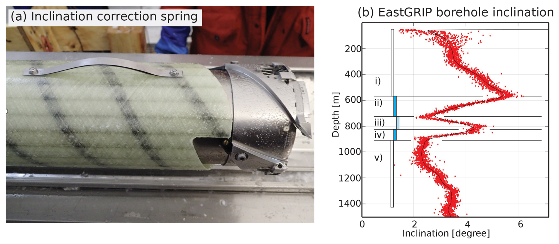
Figure 1(a) The inclination correction tool, a spring attached to the outer barrel, designed on site to decrease borehole inclination at the EastGRIP site in 2018. (b) Borehole inclination of the upper 1500 m of the EastGRIP hole (Dorthe Dahl-Jensen, personal communication, Supplement 8, 2024). (i) To increase the descent speed of the drill, a deadweight was added to the lightweight short version of the deep drill. This caused the drill's center of gravity to be above the supporting knobs, leading to a rise in the inclination when drilling. (ii) We mounted the inclination spring and repositioned the support knobs, gradually decreasing the inclination. (iii) We mounted the spring the wrong way around, and the inclination increased again. (iv) We mounted the spring in the right way again. (v) We removed the spring as the inclination was now acceptable.
1.3 Initial idea from the inclination correction tool
In 2017 and 2018, we unintentionally drilled with high inclinations in the upper sections of the EastGRIP borehole (Fig. 1b, section i). Due to the slow descent speed of our lightweight short version of the deep drill, we added a deadweight. This shifted the drill's center of gravity upwards, above the supporting knobs, leading to a rise in inclination while drilling.
To correct the high borehole inclination, we added a spring to the outer barrel (Fig. 1a), which pushed on the uphill side of the borehole – forcing the cutter head towards plumb, thus gradually decreasing the inclination (Fig. 1b, section ii). The successful implementation of this technique verified the use of our orientation package, based on the BOSCH BNO055 9-axial orientation sensor, and that slight spring pressure can slowly change the direction of the drill with depth.
We then, accidentally, mounted the spring the wrong way around, increasing the inclination of the borehole once again (Fig. 1b, section iii). Once we noticed this, we again mounted the spring in the correct orientation (Fig. 1b, section iv). At a depth of approx. 900 m the borehole inclination was acceptable and we removed the spring (Fig. 1b, section v). The borehole inclination data can be found in Supplement 8 (Dorthe Dahl-Jensen, personal communication, 2024).
The idea for our replicate drilling design is based on this inclination correction tool (Fig. 1a) and the gravitation-based milling test in the 400 m deep dry hole at NEEM (mentioned above).
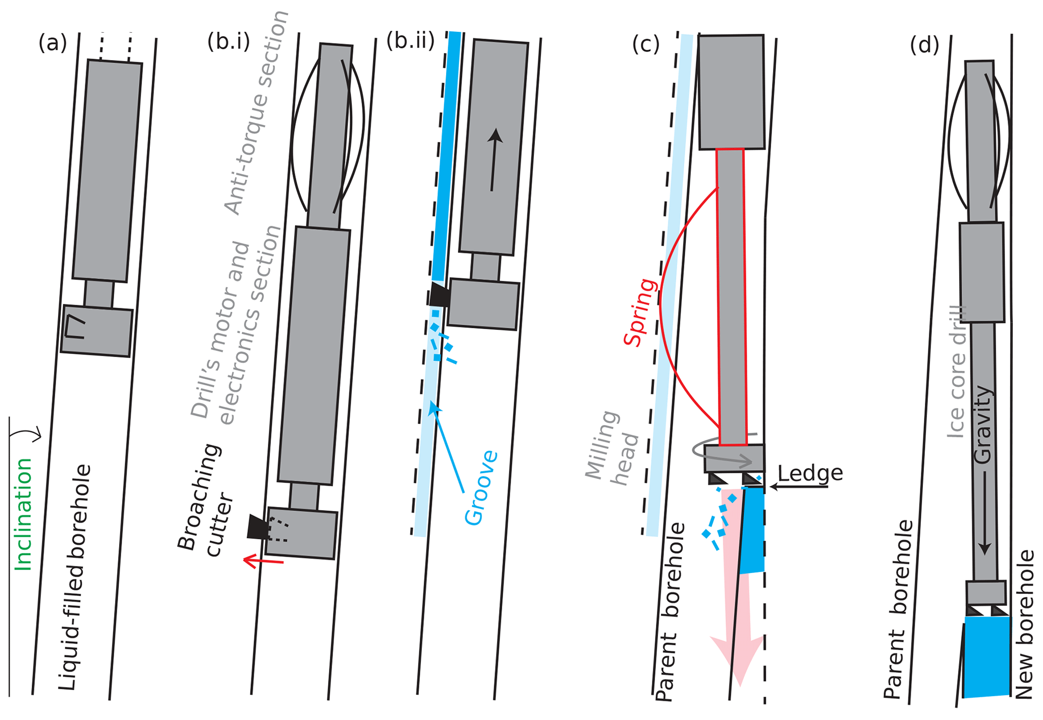
Figure 2Concept of the replicate drilling setup. (a) The broaching tool is lowered into the liquid-filled and slightly inclined borehole. (b) The cutter is engaged into the borehole wall (red arrow), and then the tool is pulled up, cutting a groove into the side of the wall. (c) The broaching tool is replaced by the spring sleeve, and the spring follows the groove (dashed line). The milling head cuts into the side of the borehole wall. (d) When lowering the ice core drill, gravity will guide it into the new borehole. In our test we did not perform step (d) but stopped at step (c).
2.1 Concept and design requirements
We tested the replicate ice-coring system in an inclined and liquid-filled borehole (Fig. 2a), yet both are not requirements for our system. The concept of the system is the following: first, we determine the spatial orientation of the borehole, then broach the “uphill” side of the hole (Fig. 2b), and then mill the side of the borehole as shown in Fig. 2c. Gravity will then guide downhole tools into the new hole (Fig. 2d).
The system needs to comply with certain operational requirements:
-
The parent hole should remain accessible. It is acceptable to deviate into the downhole side of the parent borehole. This means that gravity will guide the drill and other downhole tools into the new borehole but access to the parent hole remains.
-
The system should work in all holes with any inclination that can be drilled with a Hans Tausen (HT) style drill, yet we would prefer 2° or more. From experience, no borehole is ever perfectly plumb (0°), which eases this requirement.
-
The system should only use the HT deep-drill pressure tube and hardware for actuation and communication; i.e., the replicate hole and parent hole must have the same diameter.
-
The system must operate at temperatures down to −55 °C, e.g., for the BE-OI project.
-
Deviation from the parent borehole must be possible at any depth (below the casing).
The method of drilling a replicate core using the system presented in this paper is based on adapting the corer to incorporate three key functions. First, a retractable broaching tool cuts a vertical groove, ∼ 30 mm wide and up to 5 mm deep, along the borehole wall. Second, a spring sleeve, which bows into and slides along that groove, retains the corer in a consistent and known orientation. This spring sleeve also pushes the base of the corer laterally away from the keyway, raising the cutting head's contact force on the opposite side of the borehole wall. Third, a milling head (with the ability to cut sideways as well as downwards) is used to mill into the opposite side of the borehole wall under this enhanced force.
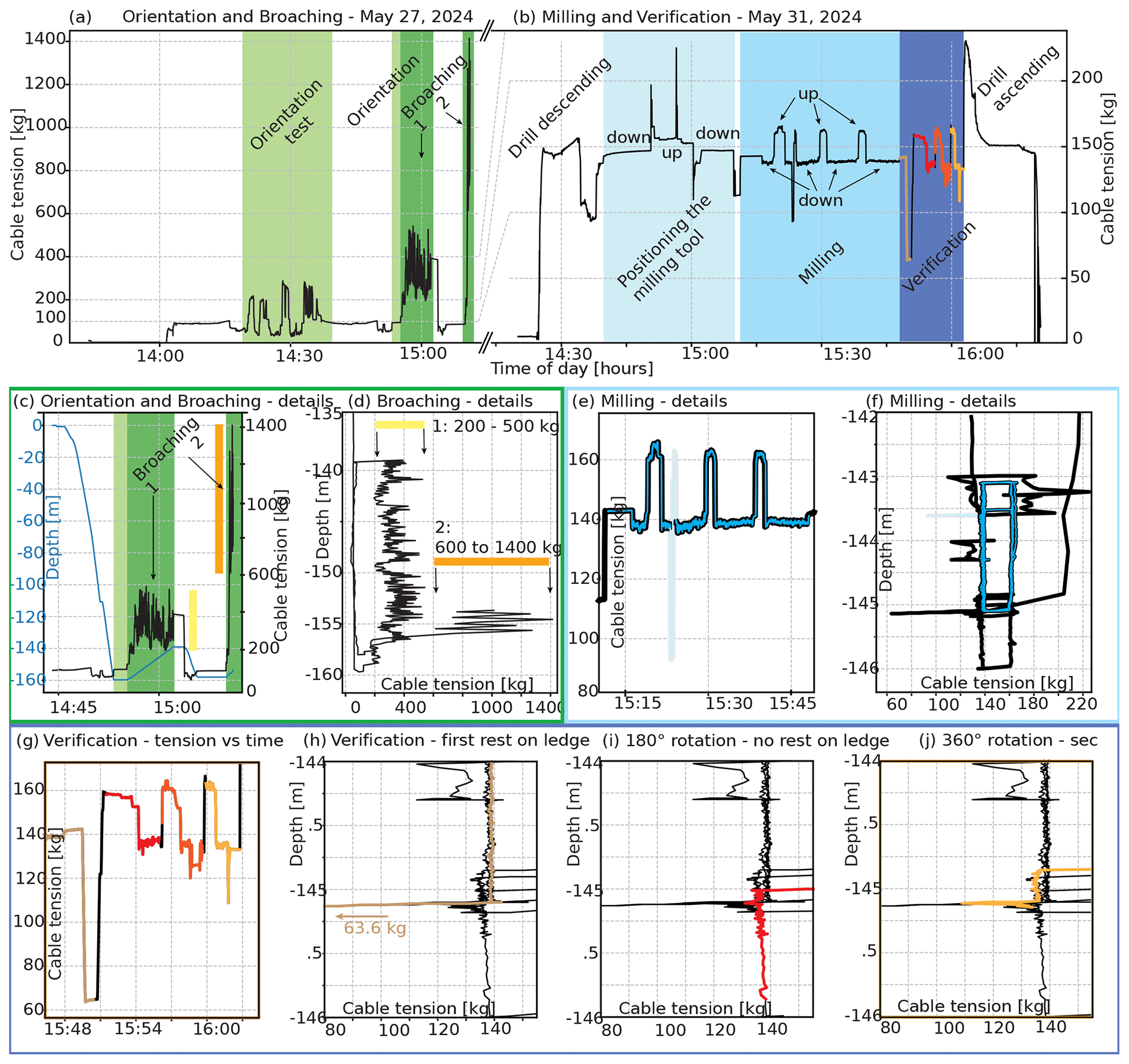
Figure 3(a, b) Overview of the orientation, broaching, milling, and verification run. (c, d) The broaching procedure in detail, including the stick slip of the broaching tool and the resulting cable tension. (e, f) The procedure of the cable extension excursions of the milling process. (g)–(j) The reduced cable tension as the drill rests on the ledge on the side of the borehole. (h, j) No drop in tension as the drill is pushed to the side of the borehole without a ledge.
2.2 System deployment and testing
On 27 May 2024, we tested the orientation around 14:30 and just prior to broaching we set the orientation of the broaching tool (Fig. 3a). We broached around 15:00. We used 28 May to clean the borehole from the chips created by broaching the side of the hole. 29 and 30 May were dedicated to other downhole activities, non-related to replicate drilling. On 31 May 2024, we first tested the process of slow milling in the morning (not plotted) and then milling at “normal” speed (milling, from 15:15 to 15:45). We verified that we had produced a ledge, just after milling, by 16:05 (Fig. 3b). The details will be discussed in the following sections.
2.3 Spatial borehole orientation
To ensure we have deviated the drill in the intended direction, we need to determine the spatial orientation of the borehole inclination relative to the drill (Fig. 2a, the timing of finding the spatial orientation is indicated in Fig. 3a and c). For deviation drilling, we will mill the “downhill” side of the borehole so that the drill glides into the “new” hole by gravity. However, for this field test, we attempted to deviate towards the top side of the borehole to prevent damage that could limit access to the bottom parts of the hole for future logging or basal measurements.
To determine the correct position of the broacher, i.e., on the bottom side of the borehole, we used the aforementioned drill orientation package included in the Danish deep-drill system, relying on the proprietary BOSCH Sensor Fusion software to calculate the BNO055 orientation quaternion, included in the Danish deep-drill system. This software supplies the inclination, azimuth, and roll of the drill. For our test, azimuth and roll were offset by 180°, meaning the orientation roll of the drill is on the opposite side of the direction of maximum inclination.
We do not plot orientation data, as the orientation is relative to the arbitrary reference of the drill tower and for more detailed orientation data (e.g., for Fig. 3g–j) the sampling speed is not high enough (see Sect. 4.2).
2.4 Broaching
2.4.1 Design of the broaching tool
In the next step, we broach the downhill side of the borehole. The purpose of broaching is to make a groove in the borehole wall that the drill will use as an orientation reference; that is, the drill will follow this groove, pushing the cutters against the other side of the borehole wall while milling. A central shaft couples directly to the output of the drill motor section (Fig. 4 and Westhoff et al., 2024). The other end of the shaft is mated to a changeable cam plate. The plate determines the overall depth of cut of the blade into the borehole wall. Supplement 2 is an example of a cam plate that can cut a nominal 10 mm deep slot. Note that there is a 45° “deadband” of rotation when the blade is fully retracted and fully protruded. The motor position must be able to be controlled to engage the blade within that band.
After the blade is protruded, a groove is cut by pulling the system upwards with the winch. The blade was designed to evacuate the chips through a hole in the center of the blade (Supplement 3).
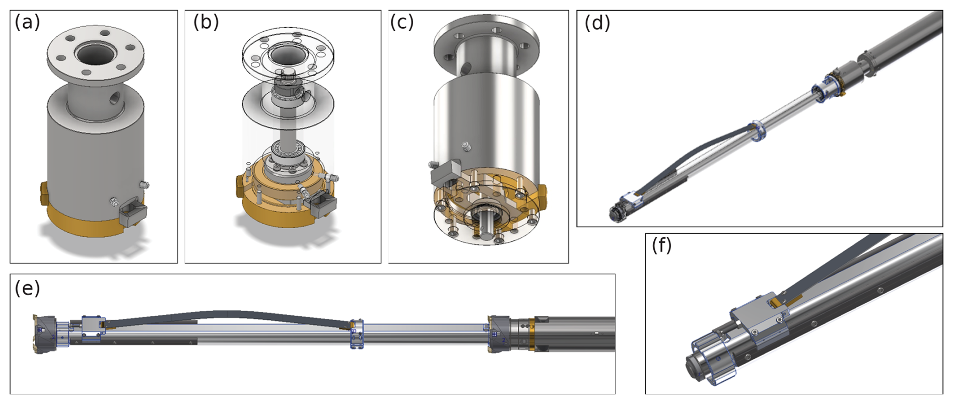
Figure 4(a, b, c) The broaching tool in detail. The extracted broaching cutter is visible on the bottom right of panel (a). (d) The optional spring below the broaching tool. (e, f) The milling head can be mounted either at the bottom or top of the spring sleeve, facing down (cut while descending) or facing up (cut while ascending). Only one milling head would be mounted at a time. The linear rail at the bottom of the spring can be limited in travel to produce lateral force, either by a bolt as shown above or by a spring for longer travel demands.
2.4.2 Planned broaching process
For the test, we broached in two steps: 2 and 5 mm deep. We used a cam plate with a total cutting depth of 5 mm. Then by rotating the motor by 90°, the first stage of the broaching tool is driven out of the housing and into the borehole wall for an approximate cutting depth of 2 mm (Fig. 2b). Note that rotating the motor by 90° does not rotate the drill but rather drives out the cam plate. The drill is then pulled up 20 m to complete the first 2 mm deep cut. After lowering the drill back to the starting depth, the motor is rotated another 90°, extending the broaching tool the full 5 mm into the side of the borehole. The drill is once again raised 20 m to complete the second cut, leaving a 5 mm deep and 30 mm wide groove. We chose these dimensions as they match the sleeve spring of the milling tool used in the next step.
2.4.3 Execution and issues
We broached the first step (2 mm depth) from 160 to 139 m depth with a cable tension between 200 and 500 kg (yellow bar in Fig. 3c, d). During the second broaching step (the full 5 mm) we reached cable tensions between 600 and 1400 kg (orange bar in Fig. 3c, d). After 5 m, the motor stopped functioning and we could not retract the blade. Therefore, we were forced to broach all the way to the surface. This was probably caused by the anti-torque (AT) slide hammer's up-and-down motion during stick slip, which broke the slip-ring connector. As the motor stopped functioning, the ascent is not recorded (upwards from approx. 154 m depth; Fig. 3c, d).
2.5 Milling
2.5.1 Design of the milling tool
Having cut a groove into the side of the borehole for orientation referencing, we lowered the second unit of the direction drilling tool down the hole: the spring sleeve (Fig. 4e, f; Supplement 4) and milling head. The spring sleeve is designed to push the milling head into the opposite side of the borehole wall. The milling head uses the force of the spring to cut sideways, eventually forming the new borehole. This technique was successfully used to create a replicate hole during the NEEM project. However, it was done in a dry borehole and relied solely on the force of gravity to press the cutters into the borehole. The spring sleeve uses an AT blade as a spring (Fig. 2c) which needs to sit in the broached slot. The spring is fixed to a collar on one end, and the other end rides on linear rails. The travel of the blade on the linear rail can be limited by a push screw or spring to ensure there is adequate lateral force for milling.
2.5.2 Orientation of the milling tool
To position the spring into the slot, we rotated the drill backward. The one-directional bearings in the assembly guarantee that the spring rotates with the shaft of the motor. When we witnessed a peak in motor power consumption, we knew the spring had dropped into the broached slot (thus the AT blades need to rotate, which requires more power to slip). For verification, we rotated the drill by 360° and again witnessed the high motor power consumption. The power consumption we witnessed was very short and only visible on the direct readings of the power supply unit (Sørensen) and not recorded by the software; the software subsamples over a couple of seconds, removing the peak in power consumption.
2.5.3 Configurations for cutting
There are several positions and configurations for the milling head on the spring sleeve, as well as several mounting options for the spring sleeve to the drill. The milling head is a standard ice-coring head, with full kerf cutters. This head can be mounted at the top or the bottom of the spring sleeve, facing up or down (Fig. 4). The spring sleeve can be mounted to the drill in three ways:
-
at the end of the hollow shaft with a one-directional bearing,
-
at the end of the core barrel with a one-directional bearing, and
-
fixed to the chip chamber.
When cutting facing downwards, we will create a sharp step for the deviation to begin; however, the chips will stay around the spring. During upwards drilling, the blade faces upwards and the chips will be left below the drill, reducing the risk of sticking the drill. For the test, we used only a downward-facing cutter at the bottom of the spring sleeve.
2.5.4 Execution
We performed the test of the replicate drilling tool on 31 May 2024, between 14:25 and 16:25 (Fig. 3b). For the cutting itself, we used two configurations of cutters to test which one performed better.
-
First, we tested a milling head with only one cutter and a very slow descent speed (not plotted). We started the drill motor and pushed the mounted milling head into the side of the wall. We slowly lowered the drill, cutting into the side of the wall. Due to very slow descent and very little cutter force, the cutting itself was not witnessable on the drill's power consumption. We milled 5 m in total: two times while lowering the drill and one time while moving the drill upwards, pushing the cutters more and more into the side of the wall with each milling run.
-
The second milling process is color-coded in blue (Fig. 3e, f) and was done between 15:15 and 15:45 on 31 May 2024. Here, we used a milling head with three normal cutters and “normal” downward drilling speed. In this case, we only milled 2 m on the side of the borehole but repeated this three times up and four times down (Fig. 3b, milling). We stopped at the same depth as with the first setup, i.e., 145.10 m depth. The sharp drop in cable tension at around 15:25 or 143.6 m depth (Fig. 3e or f, respectively, color-coded in very faint colors) is due to a short power-off of the motor yet with continuous cable payout.
We stopped every run at the same depth; this ensured that we cut out a ledge on the side of the borehole.
After milling into the borehole wall (around 15:45 in Fig. 3f), we stopped the drill and continued to pay out cable. The cable tension sharply dropped, which indicated that we were resting the drill on the ledge we had just cut into the side of the borehole (brown curve in Fig. 3g, h). We stopped at a cable tension of 63 kg, corresponding to almost 80 kg resting on the small ledge (Fig. 3g).
We raised the drill by a few tens of centimeters and then turned the blade of the replicate drilling tool, by 180°, thus forcing it to come out of the broached slot. We slowly lowered the drill, and we did not catch the ledge, as evidenced by no drop in the load (Fig. 3i, red curve). The spring was now pushing the milling head away from the ledge to the opposite side of the borehole.
For a final verification, we raised the drill approximately 30 cm above the ledge. We then rotated the spring by another 180° and ensured that it caught the broaching slot again. We then lowered the drill and again caught the ledge, resulting in a drop of the cable tension (Fig. 3j). The load did not drop as far as in the first test, possibly by degrading the integrity of the ledge by repeated contact.
This proves that we have managed to cut into the side of the borehole, and we have also managed to rest a large part of the drill's weight on this ledge. We did not perform any further replicate drilling in the borehole, as the main goal was to prove the concept.
4.1 Differences in our test compared to non-test deployment in the field
We tested the replicate drilling equipment as it is planned to be used in later projects (see Introduction); however, the test was performed on the “uphill” side of the borehole rather than the “downhole” side. We broached on the “downhill” and cut into the “uphill” side of the borehole. For deviation/replicate drilling in the future the opposite should be done to ensure the effect of gravity guides the drill into the new borehole (Fig. 2d).
Furthermore, we also recommend broaching more than 10 m, as the long ice core drill needs to get the curvature of the new direction of the borehole. The best length of broaching still needs to be determined.
For our test, we cut the ledge in the uppermost part of the borehole (140 m depth) to ensure short travel times while testing and to not disturb any bottom sections of the hole. This is not the standard procedure, and a future project needs determine the depth. In our case, cutting in the upper part created light chips that floated to the top of the liquid level, creating a plug at the air–drill fluid interface. We drilled through this plug with ease, but lighter instruments could not penetrate it.
Due to this being a test of the concept, we did not actually drill a replicate core. The fact that we were able to provide a ledge, which is the first step in deviating from the parent borehole, proves that this is possible with our setup.
4.2 Issues and future refinements
During the 5 mm broaching depth run, the connection to the drill's motor unit was lost, due to a mechanical failure, and we could not retract the broaching blade (see Sect. 2.4.3). To avoid this technical issue in the future, we plan to include a mechanical fuse to release the broaching tool and make an ascent possible, even in the event of an electronic failure in the drill.
The broach blade was designed to evacuate chips through the center of the blade – conceptually similar to an ice screw. However, the chips that were collected following this step by the borehole filter revealed very densely packed pellets. This means the chips could not easily pass through the central channel. This should be improved for future iterations.
Furthermore, the removal of chips needs to be considered. Depending on the length of the broached slot, this may need to be done in between broaching steps.
We can optionally mount the spring sleeve below the broach, with the spring fixed directly below the broaching blade (Fig. 4d). When the spring drops into the groove, it will prevent the broach from cutting a helix into the borehole while pulling up. We did not rely on this mechanism for the test reported here. Such a helix was, e.g., observed at NEEM (Hubbard and Malone, 2017, Fig. 3d).
To better document the rotation of the spring sleeve and its catch into the broached slot, we need to improve the sampling speed of the software (Sect. 2.5.2). Currently the sampling rate is not high enough to preserve the peak in power consumption when catching the slot.
We introduced a new replicate drilling technique for the Danish HT drill, intended to be deployed for future deep ice core projects at GRIP, Greenland, and Beyond EPICA (Little Dome C), Antarctica. We demonstrated that our tools and method performed in the manner we had designed them for by testing them in the EastGRIP deep borehole, Greenland. By cutting a ledge into the side of the EastGRIP borehole and resting the drill on it, we have proven that the concept works. Milling on the side of which the drill will naturally rest due to gravity will further improve the effectiveness of this technique by supplementing the force imparted by the spring sleeve with that resulting from gravity.
The technical drawings and the borehole inclination data are in Westhoff et al. (2024) (https://doi.org/10.17894/ucph.6657aa80-1cc6-4df7-b813-c8c0d5af00f7, last access: 8 September 2025). The detailed drill log, i.e., the data used to create Fig. 3, is available on request.
JW, GB, and SBH came up with the idea of the manuscript and performed the test in the field. JW wrote the manuscript with contributions from all of the authors. GB is the leading engineer for the development of the tools. NR contributed with the orientation component. SBH came up with the tooling concept and the first directional tests in previous years.
The contact author has declared that none of the authors has any competing interests.
Publisher’s note: Copernicus Publications remains neutral with regard to jurisdictional claims made in the text, published maps, institutional affiliations, or any other geographical representation in this paper. While Copernicus Publications makes every effort to include appropriate place names, the final responsibility lies with the authors.
We want to thank the EastGRIP, Beyond EPICA, and Green2ice projects for their financial and logistical support as well as the Novo Nordisk Foundation for its support through the salaries.
EastGRIP is supported by funding agencies and institutions in Denmark (A. P. Møller Foundation and the University of Copenhagen), the USA (the US National Science Foundation and the Office of Polar Programs), Germany (the Alfred Wegener Institute and the Helmholtz Centre for Polar and Marine Research), Japan (National Institute of Polar Research and Arctic Challenge for Sustainability), Norway (University of Bergen and Trond Mohn Foundation), Switzerland (Swiss National Science Foundation), France (French Polar Institute Paul-Emile Victor and the Institute for Geosciences and Environmental Research), Canada (University of Manitoba), and China (Chinese Academy of Sciences and Beijing Normal University). This research has been supported by the EU Horizon 2020 research and innovation program and coordination and support action: Beyond EPICA (grant no. 815384) and BE-OI (grant no. 730258). The Green2ice project provided funding for this project through the European Union (ERC, Green2Ice, grant no. 101072180). The views and opinions expressed are however those of the author(s) only and do not necessarily reflect those of the European Union or the European Research Council Executive Agency. Neither the European Union nor the granting authority can be held responsible for them. The research leading to these results has received funding from the Novo Nordisk Foundation; grant no. NNF23OC0081251.
This paper was edited by Adam Booth and reviewed by Bryn Hubbard and Jay Johnson.
Chung, A., Parrenin, F., Mulvaney, R., Vittuari, L., Frezzotti, M., Zanutta, A., Lilien, D. A., Cavitte, M. G. P., and Eisen, O.: Age, thinning and spatial origin of the Beyond EPICA ice from a 2.5D ice flow model, EGUsphere [preprint], https://doi.org/10.5194/egusphere-2024-1650, 2024.
Greenland Ice-core Project (GRIP) Members: Climate instability during the last interglacial period recorded in the GRIP ice core, Nature, 364, 203–207, https://doi.org/10.1038/364203a0, 1993.
Hubbard, B. and Malone, T.: Optical-televiewer-based logging of the uppermost 630 m of the NEEM deep ice borehole, Greenland, Ann. Glaciol., 54, 83–89, https://doi.org/10.3189/2013AoG64A201, 2017.
Popp, T. J., Hansen, S. B., Sheldon, S. G., and Panton, C.: Deep ice-core drilling performance and experience at NEEM, Greenland, Ann. Glaciol., 55, 53–64, https://doi.org/10.3189/2014AoG68A042, 2014.
Shturmakov, A. J., Lebar, D. A., and Bentley, C. R.: DISC drill and replicate coring system: a new era in deep ice drilling engineering, Ann. Glaciol., 55, 189–198, https://doi.org/10.3189/2014AoG68A017, 2014.
Vasiliev, N. I., Talalay, P. G., Bobin, N. E., Chistyakov, V. K., Zubkov, V. M., Krasilev, A. V., Dmitriev, A. N., Yankilevich, S. V., and Lipenkov, V. Y.: Deep drilling at Vostok station, Antarctica: history and recent events, Ann. Glaciol., 47, 10–23, https://doi.org/10.3189/172756407786857776, 2007.
Westhoff, J., Boeckmann, G. V., Rathmann, N. M., and Hansen, S. B.: Supplement to The Danish Replicate Drilling System – Results from the First Field Test, University of Copenhagen [data set], https://doi.org/10.17894/ucph.6657aa80-1cc6-4df7-b813-c8c0d5af00f7, 2024.