the Creative Commons Attribution 4.0 License.
the Creative Commons Attribution 4.0 License.
 | 24 Jul 2024
Research into mechanical modeling based on characteristics of the fracture mechanics of ice cutting for scientific drilling in polar regions
Xinyu Lv
Zhihao Cui
Ting Wang
Yumin Wen
An Liu
Rusheng Wang
Scientific drilling in polar regions plays a crucial role in obtaining ice cores and using them to understand climate change and to study the dynamics of polar ice sheets and their impact on global environmental changes (sea level, ocean current cycle, atmospheric circulation, etc.). Mechanical rotary cutting is a widely used drilling method that drives the cutter to rotate to cut and drill through ice layers. It is necessary to conduct in-depth research on the brittle fracture behavior of ice and mechanical model and to analyze the factors and specific mechanisms (cutter's angle, rotation speed of the drill bit, and cutting depth) affecting cutting force for the rational design of ice core drill systems, improving the efficiency of ice core drilling and ensuring the drilling process runs smoothly. Therefore, in this paper, the process of ice cutting was observed, the fracture mechanics characteristics of the ice cutting process were analyzed, the formation process of ice chips was divided into three stages, and a mathematical model for the cutting force was established based on the observation results. The paper describes the damage conditions of ice failure and points out the factors and specific laws influencing cutting force. Furthermore, the cutting force generated under various experimental conditions was tested. Based on specified real-time variation curves of cutting force, the characteristics of cutting force were analyzed during the cutting and drilling process. Based on comparison to results of the average cutting force, the influence mechanism of various parameters acting on the cutting force was obtained. This proves the correctness of the mathematical model of the cutting force and provides a theoretical reference for the calculation of the cutting force during ice cutting and drilling in polar regions.
- Article
(2975 KB) - Full-text XML
- BibTeX
- EndNote


As the largest cold source on Earth, polar ice sheets and glaciers are an important component of the Earth system related to Earth's crust, glaciers, ice shelves, oceans, and atmosphere, which has a profound impact on global changes such as climate change and sea level rise (Yang et al., 2023). Many scientific issues related to polar regions can be solved and validated by carrying out scientific drilling in ice sheets and obtaining ice cores (Azuma et al., 2014; Talalay et al., 2015; Cao et al., 2019). Mechanical rotary drills have been widely used in the field of polar ice core drilling (Ueda and Garfield, 1968, 1969; Gundestrup and Johnsen, 1984; Kudryashov et al., 1994; Wumkes, 1994; Shturmakov et al., 2007). The process of ice core drilling mainly consists of three steps: cutting and drilling of the ice sheet, removal and transport of the ice chips generated at the hole bottom, and collection of ice core and chip precipitation (Litvinenko and Vasiliev et al., 2014). These three steps are interrelated, and all of them have significant effects on the process of drilling. The cutting and drilling of the ice sheet generate a cutting force, which affects not only the selection of the motor system of the drill but also the design of the anti-torsion system and even determines the success or failure of the cutting and drilling of the ice sheet. By conducting in-depth research on the fracture mechanics characteristics of solid ice, establishing a mechanical model for ice cutting, and determining the factors and specific mechanisms affecting cutting force, we can contribute to the rational design of the drilling tool system, the improvement of drilling efficiency, and ensuring the smooth progress of drilling.
During ice core drilling, ice cutting is periodically carried out. At first, the moving cutters cut into the ice and compress it. When the level of stress near the edge of the cutter exceeds the cutting point, a crack is formed in the direction from the edge to the surface. This means that the horizontal force of cutting, called Px, creates a repeated series of breaks, and its value is considered to be the mean force over the cutting length. Griffith’s strength theory assumed that when the energy of elastic strain exceeds the surface energy, the existing micro-crack starts to extend like an avalanche, and the materials break. Mellor and Sellman (1975) suggested that the cutting force Px can be calculated using specific energy ES (N m−2), which is the energy consumed per unit of cutting volume:
where b is the width of the cutter and h is the depth of cut.
Using Eq. (1) to calculate cutting force is difficult because specific energy is a vague concept. The equation ignores the influence of the structure of the cutter on the cutting force and lacks a certain degree of practicality. Due to the difficulty of conducting strict theoretical methods for the design of rock-cutting machines, many of the same experimental methods were developed by Atabey et al. (2003). Wang et al. (2023) assumed that in any deformation process caused by compression, tension, bending, or cutting, the mechanics of ice failure are determined by the processes of inter- or intragrain sliding. Taking the ideal monocrystal of ice, the theoretical stress needed for the formation of sliding zones is near 100 MPa, but for real ice, it does not exceed 0.1–0.5 MPa (Leppäranta and Hakala, 1992). The contradiction is explained by disposition theory. According to this theory, the deformation of the ice is determined by the defects which already exist in the ice crystal. The internal defects gradually expand under the action of external forces, and ice destruction occurs. Due to non-uniformity, hard brittle properties, and the factors that affect cutting resistance being complex, most studies on solid ice are conducted to investigate the influence of a certain variable on cutting resistance (Chiaia et al., 2008; Hell et al., 2014; Correas et al., 2022). The in-depth study of the cutting properties of solid ice has rarely been reported.
In this paper, images of the cutting and drilling process of the ice under various experimental conditions are captured, the fracture mechanics characteristics of the ice cutting process are analyzed, and the formation process of ice chips is clarified and divided into three stages. Based on the results, a mechanics and mathematical model of ice cutting is built, and the factors and specific laws influencing cutting force are analyzed. Finally, the influencing factors and laws are verified through experimental tests, providing a theoretical reference for the calculation of cutting force during ice cutting and drilling.
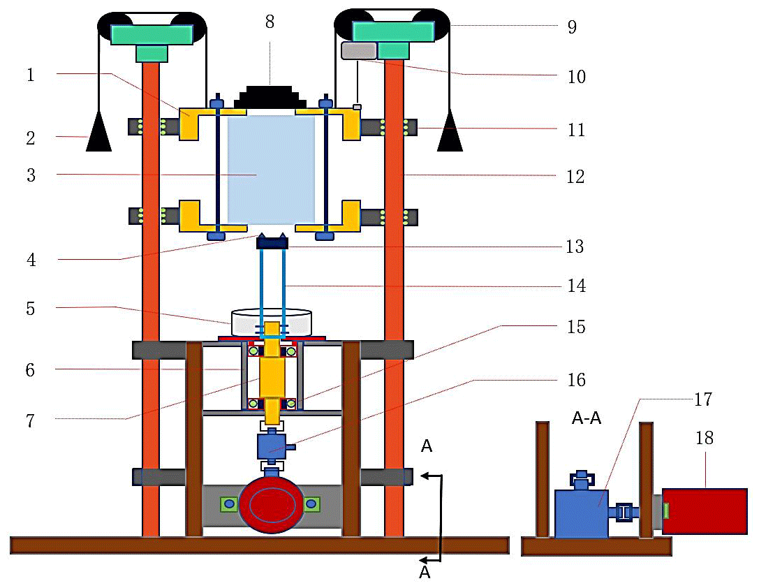
Figure 1Schematic diagram of the experimental platform: 1 – ice box; 2 – balance weight 1; 3 – ice block; 4 – cutter; 5 – ice chip collector; 6 – cup set; 7 – stepped shaft; 8 – dead weight; 9 – fixed pulley; 10 – draw-wire displacement sensor; 11 – slider; 12 – slide rail; 13 – drill bit; 14 – drill pipe; 15 – bearing; 16 – torque sensor; 17 – directional converter; and 18 – servomotor. A–A represents the observation direction of the diagram.
2.1 Test stand design for study on the ice cutting process
To observe the cutting and drilling process of the ice under various experimental conditions, an ice cutting and drilling simulation test stand has been designed (Fig. 1).
To ensure the ice cutting and drilling proceed smoothly and the weight on the drill bit is constant during the drilling process, the drilling direction is inverted upward. Therefore, the ice chips generated in the drilling process fall directly into the ice chip collector due to gravity and there is no adhesion or blockage on the drill bit. During the experimental process, the ice block and ice box can slide nearly without friction as they are connected to two parallel slide rails through four sliders, and the slider is equipped with rolling balls inside to ensure that the slider slides almost without friction on the slide rail. Therefore, during the drilling process, constant drilling pressure can be ensured, and multiple drilling pressure tests can be achieved by increasing or decreasing the balance weight and dead weight. The drill pipe, drill bit, and cutters are driven to rotate by the servomotor system, and its rotation speed can be adjusted arbitrarily between 0–1000 rpm. In this way, the adjustment of the rotation speed of the drill bit is achieved. The cutter equipped in the experimental test stand can be replaced arbitrarily according to the experimental requirements; therefore, it is possible to conduct cutting and drilling tests on cutters with various structures.
During the experiment, the torque generated by driving the rotation of drill pipes, step shafts, and other components, as well as the cutting torque generated by ice cutting, is measured by the torque sensor. Before conducting the cutting and drilling experiment, the rotation speed of the drill bit must be adjusted to the rotation speed for the next experiment and a blank run conducted with the drill bit and other components. After the torque measured by the torque sensor stabilizes, the torque is recorded as T1. Next, cutting and drilling are performed. After the cutting and drilling process stabilizes, the recording of cutting torque begins. After the drilling process, the average cutting torque during this period is recorded as T2. Therefore, the torque for ice block cutting Tc can be calculated according to the following equation:
The drilling depth and time are measured by the draw-wire displacement sensor. The formation process of ice chips is captured by a high-speed camera.
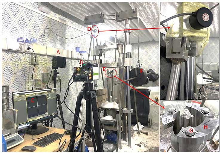
Figure 2Test stand: A – light source; B – high-speed camera; C – image display computer; D – draw-wire displacement sensor; E – drill bit; F – counterweight block; G – drill bit shoe; and H – cutter.
2.2 Test stand building and observation of ice fissure propagation during ice core drilling testing
Based on the above working principle, the ice core drilling test stand was established (Fig. 2).
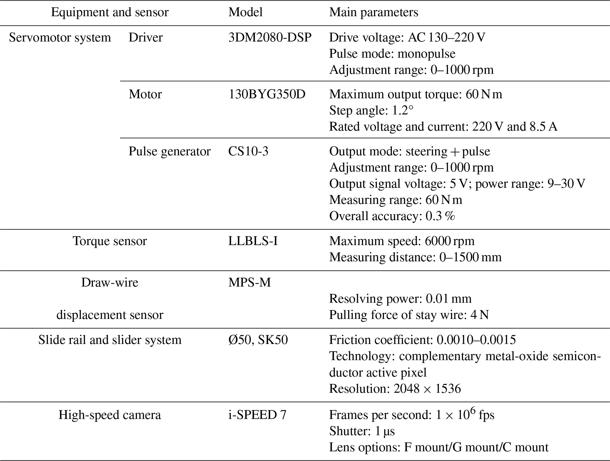
The specific parameters of the main equipment in the test stand are shown in Table 1.
Before the experiment, the cutters (Fig. 2H) made from tool steel (W18Cr4V) are installed on the drill bit (Fig. 2E) through bolts and pins (Fig. 2H) that also serve as the shoes with adjustable height. The height of the bolts is lower than the height of the cutter's tip when the ice block slides into contact with the shoes; the cutters have been cut into the ice block at the designed depth. Thus, the cutting and drilling at the designed cutting depth are achieved and the cutting depth is accurately controlled.
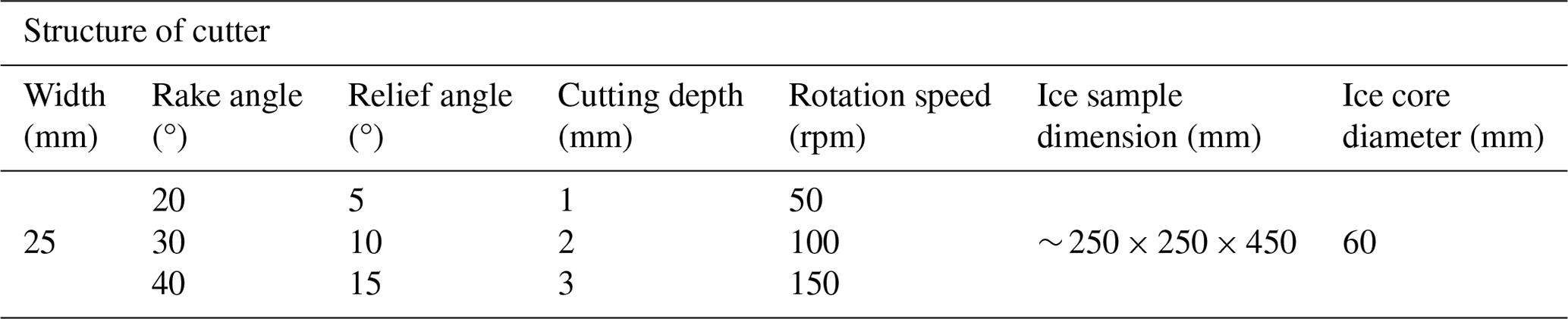
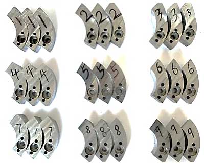
The high-speed camera (Fig. 2B) is aimed at the cutting edge of the cutter, with its frame number adjusted to 100 000; meanwhile, the light on the object is supplemented with the light source (Fig. 2A), until the image displayed on the computer (Fig. 2C) is clear. After the experiment, the images of the formation process of ice chips are captured and saved on the high-speed camera. The observation experiment of the cutting and drilling process is conducted under various experimental conditions (multiple cutter angles, cutting depths, and rotation speeds of the drill bit). The specific parameters of experimental conditions are shown in Table 2. The cutters used in the experimental process are processed with wire-cut technology. Before the experiment, to prevent the impact of surface burrs, slag, and surface roughness on the test results, sandpaper with 1000 mesh, 1500 mesh, and 2000 mesh is selected to manually polish the surface of the cutter until it is smooth. After each test, the surface and cutting edge of the cutter are observed; if there is wear or damage, the cutter is polished or replaced directly. The cutters tested in the experiment are shown in Fig. 3.
This study mainly focuses on the establishment of a mechanical model during the ice cutting and drilling process. Studies have shown that the crystal orientation, the crystal size, and the density of ice samples in NGRIP boreholes in Greenland are similar to those of naturally formed and artificially frozen ice samples (Ruth, 2003). Moreover, many scholars have conducted experiments on artificially prepared or naturally formed ice samples and have ultimately obtained convincing experimental data and conclusions, providing valuable references for research in the polar field (Talalay, 2003; Hong et al., 2015; Wang et al., 2024). In order to better observe the formation process of ice chips, this study selected transparent ice and explored the fracture process and cutting force generated by this type of ice. The ice with a variety of properties belongs to the category of brittle materials, and there will be similarities in the fracture process. In the future, cutting and drilling experiments with different ice sample properties to explore the effect of ice properties on the cutting force will be carried out. The ice blocks used in this experiment are frozen by an ice-making machine (Fig. 4), which can produce transparent ice samples without bubbles. We divided these blocks into experimental ice blocks with uniform dimensions (Fig. 5) of ∼ 250 mm × 250 mm × 450 mm, and all tests were carried out in a refrigerated container with a constant temperature of −15 °C.
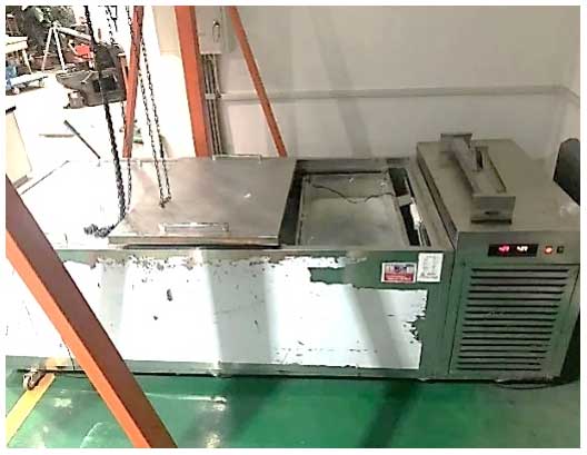
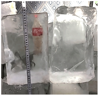
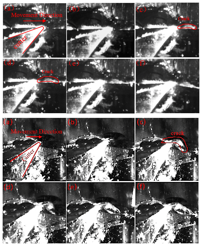
Figure 6The cutting process captured by the high-speed video camera; up (rake angle is 40°, relief angle is 15°, cutting depth is 1 mm, and rotation speed of the drill bit is 100 rpm) and down (rake angle is 30°, relief angle is 25°, cutting depth is 2 mm, and rotation speed of the drill bit is 100 rpm).
Ice cutting is preliminarily observed after the mechanical testing of ice under the specified experimental conditions. The actual ice cutting process captured by a high-speed camera is shown in Fig. 6.
Compared with the cutting and drilling process at a cutting depth of 1 mm, when cutting and drilling at a cutting depth of 2 mm, the depth of the cutter inserted into the ice sample increases, resulting in more small-particle ice chips. The particle size of the ice chips formed by major fracture increases, and the surface after cutting becomes more uneven.
Under various experimental conditions, the ice cutting process is similar. In the cutting process, the cutting of the ice is constantly repeated, the main damaged form of ice is a brittle fracture, the chips show a wedge block form with no significant deformation, and wedge-shaped ice chips with different particle sizes are constantly formed under a variety of experimental conditions. The formation process of a single large particle of ice chips can be divided into three stages. In the first stage, the cutter cuts the ice and the ice is compressed by the rake and relief surfaces of the cutter, resulting in ice crushing and smaller-ice-chip formation (Fig. 6a and b). In the second stage, with the rotation of the drill bit, cracks appear in the ice, and the cracks begin to expand along a direction that is at an angle of approximately 45° to the horizontal direction (Fig. 6c and d). However, there are no gaps or separations between the ice and cutters on both sides of the cracks. In the third stage, the cutter moves forward, the crack expands to form ice chips with large particle sizes that slide forward, and these are finally detached from the ice. At the same time, ice chips with small particle sizes are also generated on the sliding surface (Fig. 6e and f).
4.1 Mechanical model building based on the characteristics of ice fracture mechanics
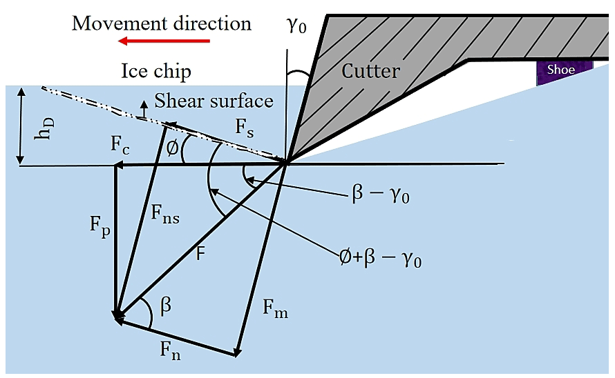
According to the observation results of the ice cutting, the damage to the ice can be considered the result of shear-slip failure caused by the compression effect of the cutter. In this process, the force exerted on the ice chips mainly includes the squeezing force Fn towards the ice and along the normal direction of the cutter's rake face. The frictional force Fm is exerted by the cutter when the ice chips flow out; at the same time, the shear surface of the ice is also subjected to normal pressure Fns and shear force Fs. Before the cutting of the ice, these two pairs of forces are in equilibrium. The relationships between these forces are analyzed in front of the cutting edge (Fig. 7).
F is the combined force of Fm and Fn; ∅ is the shear angle; β (friction angle) is the angle between Fn and F; γ0 is the rake angle of the cutter; and Fp is the component force perpendicular to the movement direction of the cutter, which is applied to the cutter and mainly provided by the weight on the drill bit during the ice layer cutting and drilling and causes the cutter to cut into the ice to a certain depth. During the cutting and drilling process, the cutter comes into contact with the ice sample before the shoes. Only when the cutter is inserted into the ice layer with the designed cutting depth will the shoes fully contact the bottom of the borehole. Prior to this, there will be continuous Fp on the cutter. As the drill bit rotates, the cutter always inserts the ice sample before the shoe, and the Fp on the cutter will continue to exist. Where Fc is the component force acting on the ice layer and during the ice layer cutting and drilling process, this force is mainly provided by the motor, which is called the cutting force. hD is the cutting thickness. If the cutting width is represented by bD, with the cutting width representing the width of the annular gap between the ice core and the hole wall in the process of ice drilling (cutting width, width of the cutter); the area of the nominal cross section of the cutting layer is represented by AD (AD=hDbD); the area of shear surface is represented by As (); and the shear stress on the shear plane is represented by τ, then
According to Fig. 7, it can be concluded that
According to the relationship between various forces, it can be concluded that
4.2 Analysis of factors influencing cutting forces via the mechanical model
According to Fig. 7, there is no shear stress in the plane perpendicular to the combined force F, so the main stress is completely determined by F. If the material is in the state of plane stress, the included angle between the direction of the maximum shear stress and the direction of the maximum principal stress is 45°, and the included angle between the maximum principal stress and the F is 45°, then
Therefore,
The shear angle ∅ is affected by the rake angle of the cutter γ0 and friction angle β. As the rake angle of the cutter γ0 increases, the shear angle ∅ increases; as the friction angle β increases, ∅ decreases.
The area of the nominal cross section of the cutting layer is represented by AD (AD=hDbD), the area of the shear surface is represented by As (), and the shear stress on the shear plane is represented by τ. Then, according to Eq. (5) and the relationship between the nominal cross section and the shear plane, the following can be obtained: that
When the ice is about to break, the shear stress on the shear plane reaches its maximum value. This value is determined by the properties of the ice and will not change according to the drilling conditions. Therefore, the cutting force is influenced by the cutting width of the cutter and the cutting depth. The cutting force shows a linear increasing trend with the increase in the cutting width and the cutting depth. In addition, the cutting force is also affected by the shear angle ∅, friction angle β, and cutter's rake angle γ0. The friction angle β is a certain value because of the properties of the ice and cutter's material. The shear angle ∅ is determined by the friction angle and the cutter's rake angle as shown in Eq. (9). Substituting Eq. (9) into Eq. (10) and solving for the combined cutting force Fc, the following equation can be given:
After simplifying the above equation, the following can be obtained:
It can be seen from Eq. (12) that the factors affecting the cutting force mainly consist of four aspects. The first aspect is related to the shear strength of the ice: with the increase in shear strength, the cutting force increases gradually. The second aspect is influenced by the cutting depth: with the increase in cutting depth, the cutting force increases gradually. The third aspect is affected by the cutting width: with the increase in cutting width, the cutting force increases gradually. Finally, the rake angle of the cutter also has an impact on the cutting force. Under the condition of , as the rake angle of the cutter γ0 increases, β−γ0 gradually decreases, tan (β−γ0) decreases, increases, and Fc decreases.
5.1 Analysis of the characteristics of the cutting force
To verify the theoretical analysis results of the factors affecting the cutting force, the cutting torque collected by the torque sensor under various cutter angles, rotation speeds of the drill bit, and cutting depth conditions was measured.
After the experiment, the torque for ice cutting and drilling can be obtained through Eq. (2). The schematic diagram of the torque and cutting force generated during the ice cutting drilling process is shown in Fig. 8. The relationship between the cutting force Fc generated by cutting the area of the circular ring and the torque Tc measured by the torque sensor is as follows:
where rA is the average radius of the circular ring.
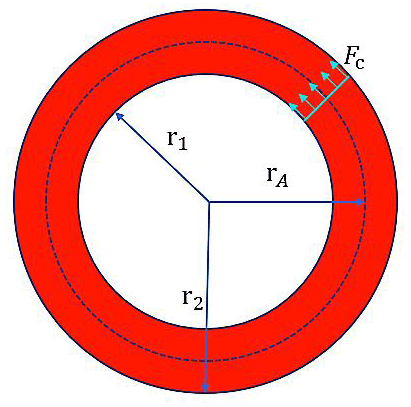
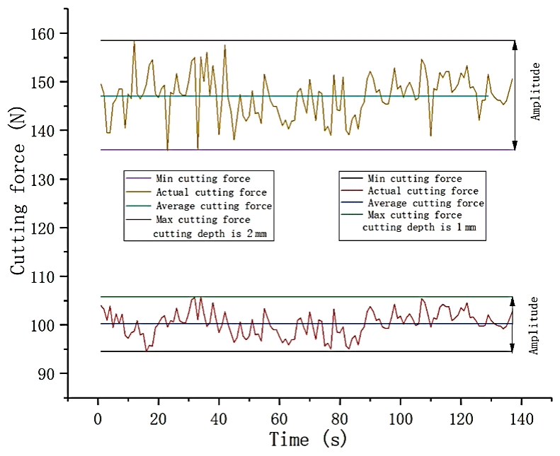
Figure 9Typical cutting force trace (cutting depth is 1 and 2 mm; rotation speed of drill bit is 50 rpm; rake angle is 30°; relief angle is 5°).
By processing the data collected by the torque sensor, the cutting force generated by one cutter during the ice block cutting and drilling is obtained. The typical cutting force trace generated during the ice cutting process is shown in Fig. 9.
Figure 9 shows the cutting force trace generated during two cutting and drilling processes, which were carried out under the same conditions except for cutting depth; both cutting force traces oscillate at a certain frequency within a certain range, and the oscillation consists primarily of two frequencies. In addition the oscillation frequencies of two cutting force traces are similar. The higher frequency is related to the resolution of the sensor. The sensor outputs data at a certain interval during the recording process; the output data are not continuous, resulting in fluctuations in the trace. The lower frequency is related to the formation of large-particle ice chips. Unlike ductile materials, where the chips produced by a shearing action are produced continuously and the forces appear to be relatively constant, chips from brittle materials are produced by a repeated series of breaks. When the cutter is pressed into the ice, the cutting force begins to rise and elastic energy is stored in the cutter assembly. Some of the energy is expended in local crushing, and the ice layer undergoes shear-slip deformation. As the cutting force reaches a magnitude necessary to induce a major fracture, a crack propagates into the ice, releasing the cutter elastic energy and dislodging a major chip; the force than suddenly decreases. Therefore, during the cutting and drilling process in the ice layer, the cutting force trace exhibits an oscillating state, and the amplitude of the oscillation is related to the cutting depth. During the process of the cutting depth increase, the degree of the rapid increase and decrease in the cutting force will be more severe. As show in Fig. 9, when drilling with a cutting depth of 2 mm, the oscillation amplitude of cutting force is greater than that of drilling with a cutting depth of 1 mm.
As the cutting depth increases, the degree of crack propagation into the ice will also increase. When the crack extends into the ice core, it will cause a decrease in the surface quality of the ice core. It is necessary to control the cutting depth reasonably during the cutting process to ensure the quality of the ice core. Moreover, Eq. (12) indicates that under the condition of , the cutting force gradually decreases with the increase in the rake angle. The rake angle can be appropriately increased within this range to reduce the oscillation.
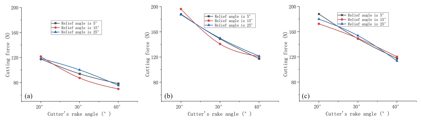
Figure 10Cutting force versus cutter's rake angle. (a) The cutting depth is 1 mm, and the rotation speed of the drill bit is 100 rpm. (b) The cutting depth is 2 mm, and the rotation speed of the drill bit is 100 rpm. (c) The cutting depth is 2 mm, and the rotation speed of the drill bit is 50 rpm.
5.2 Test of the factors influencing the cutting force
After the cutting and drilling experiments, the average cutting force was obtained under each experimental condition. Plots of the average cutting force versus the cutter's rake angle are shown in Fig. 10.
As shown in Fig. 10, when the cutting depth is 2 mm, the rotation speed of the drill bit is 100 rpm, the rake angle of the cutter is 20°, and the cutting force reaches a maximum value of 196.3451 N. When the cutting depth is 1 mm, the rotation speed of the drill bit is 100 rpm, the rake angle of the cutter is 40°, and the cutting force reaches a minimum value of 69.83529 N. The cutting force varies within this range under the other experimental conditions. That is, under various cutting depths and drill speed conditions, the cutting force gradually decreases with the increase in the cutter's rake angle.
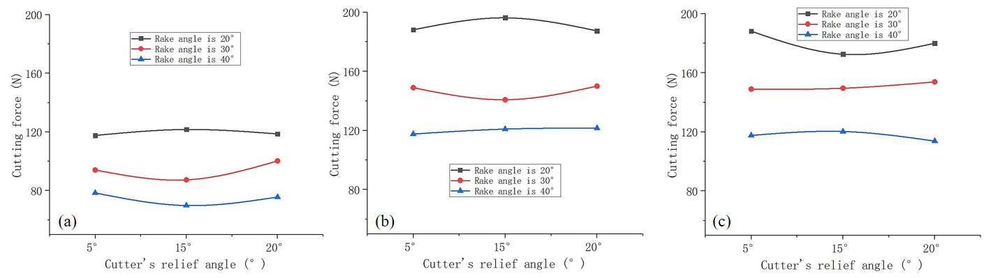
Figure 11Cutting force versus cutter's relief angle. (a) The cutting depth is 1 mm, and the rotation speed of the drill bit is 100 rpm. (b) The cutting depth is 2 mm, and the rotation speed of the drill bit is 100 rpm. (c) The cutting depth is 2 mm, and the rotation speed of the drill bit is 50 rpm.
Plots of the average cutting force versus the cutter's relief angle are shown in Fig. 11.
Under various experimental conditions, the relief angle of the cutter changes and the cutting force only changes slightly. Moreover, with the change in the relief angle of the cutter, the cutting force does not show a clear and consistent change pattern. Therefore, it can be inferred that the relief angle of the cutter has no clear effect on the cutting force.
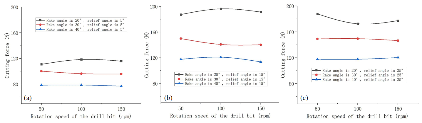
Figure 12Cutting force versus rotation speed of the drill bit. (a) The cutting depth is 1 mm. (b) The cutting depth is 2 mm. (c) The cutting depth is 2 mm.
Plots of the average cutting force versus the rotation speed of the drill bit are shown in Fig. 12.
Under various experimental conditions, there is only a slight change in the cutting force during the process of the rotation speed changing and there is no clear pattern of change. The rotation speed of the drill bit does not affect the cutting force.
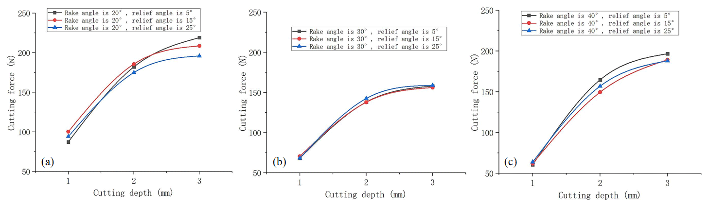
Figure 13Cutting force versus cutting depth. (a) The rotation speed of the drill bit is 50 rpm. (b) The rotation speed of the drill bit is 100 rpm. (c) The rotation speed of the drill bit is 100 rpm.
Plots of the average cutting force versus cutting depth are shown in Fig. 13.
Under all experimental conditions, as the cutting depth increases, the cutting force shows a gradually increasing trend. When the cutting depth is 3 mm, the maximum cutting force reaches 219.13725 N. Under the same experimental conditions, the cutting depth increasing from 1 to 2 mm results in an approximate doubling of the cutting force. As the depth of penetration increases, the cutting force continues to increase, but the increasing trend gradually weakens.
It is preliminarily observed after the mechanical testing of ice that the main damage form of ice is a brittle fracture in the cutting process. During this process, the cutters press into the ice to a certain depth and rotate, the ice withstands a squeezing effect from the rake face of the cutter, and the shear-slip deformation occurs. When the shear-slip deformation reaches a certain degree, the ice undergoes shear failure and then forms ice chips. This process is constantly repeated throughout the cutting and drilling of the ice.
Based on the characteristics of ice cutting and the stress characteristics during the ice cutting and drilling process, a mechanical model of ice cutting was established. The mechanical model shows that the cutting force is affected not only by the mechanical properties of ice but also by the cutting width, cutting depth, and rake angle of the cutter. As the cutting width and cutting depth increase, the cutting force increases; as the rake angle of the cutter increases, the cutting force decreases. Additionally, the characteristics of cutting force were analyzed through experimental methods. The experimental results show that the cutting force traces oscillated within a certain range; the oscillation consists primarily of two frequencies. The higher frequency is related to the resolution of the sensor, and the lower frequency is related to the formation of large-particle ice chips. The oscillation amplitude of the cutting force traces is related to the cutting depth: as the cutting depth increases, the oscillation amplitude of the trajectory will also increase. In addition, the oscillation amplitude will also affect the quality of the core: as the amplitude increases, the possibility of the ice core breaking will also increase and the quality of the ice core increase accordingly. It is necessary to control the cutting depth reasonably during the cutting process to ensure the quality of the ice core. Finally, the influencing factors and laws of the cutting force were verified by analyzing the cutting force generated under various experimental conditions.
Data are available upon request to the corresponding author.
XL: conceptualization, methodology, writing (original draft). ZC: methodology, validation, formal analysis, visualization. TW: methodology, validation, formal analysis, visualization. YW: conceptualization, writing (review and editing), methodology, validation. AL: methodology, validation, formal analysis, visualization. RW: methodology, formal analysis, supervision, project administration, funding acquisition.
The contact author has declared that none of the authors has any competing interests.
Publisher's note: Copernicus Publications remains neutral with regard to jurisdictional claims made in the text, published maps, institutional affiliations, or any other geographical representation in this paper. While Copernicus Publications makes every effort to include appropriate place names, the final responsibility lies with the authors.
This article is part of the special issue “Ice core science at the three poles (CP/TC inter-journal SI)”. It is a result of the IPICS 3rd Open Science Conference, Crans-Montana, Switzerland, 2–7 October 2022.
This paper presents research conducted with support from the National Key R&D Program of China (project no. 2021YFA0719100; subject no. 2021YFA0719103) and Jilin University “Interdisciplinary Integration and Innovation” project (project no. 419021421601).
This paper was edited by Jay Johnson and reviewed by two anonymous referees.
Atabey, F., Lazoglu, I., and Altintas, Y.: Mechanics of boring processes – Part I, Int. J. Mach. Tool. Manu., 43, 463–476, https://doi.org/10.1016/S0890-6955(02)00276-6, 2003.
Azuma, N., Faria, S. H., and Weikusat, I.: The microstructure of polar ice. Part I: Highlights from ice core research, J. Struct. Geol., 6, 2–20, https://doi.org/10.1016/j.jsg.2013.09.010, 2014.
Cao, P. L., Cao, H. Y., and Cao, J. E., Liu, M. M., and Chen, B. Y.: Studies on pneumatic transport of ice cores in reverse circulation air drilling, Powder Technol., 356, 50–59, https://doi.org/10.1016/j.powtec.2019.08.001, 2019.
Chiaia, B. M., Cornetti, P., and Frigo, B.: Triggering of dry snow slab avalanches: stress versus fracture mechanical approach, Cold Reg. Sci. Technol., 53, 170–178, https://doi.org/10.1016/j.coldregions.2007.08.003, 2008.
Correas, A. C., Cornetti, P., Corrado, M., and Sapora, A.: Dynamic crack initiation by Finite Fracture Mechanics, Procedia Structural Integrity, 42, 952–957, https://doi.org/10.1016/j.prostr.2022.12.120, 2022.
Gundestrup, N. S., Johnsen, S. J., and Reeh, N., ISTUK: A Deep Ice Core drill System [R], USA CRREL Spec. Rep. 84-34, Hanover, USA CRREL, 7–19, https://xueshu.baidu.com/usercenter/paper/show?paperid=607fb302823b28507c5ea06c209d65e3 (last access: 16 July 2024), 1984.
Hell, S., Weißgraeber, P., Felger, J., and Becker,W.: A coupled stress and energy criterion for the assessment of crack initiation in single lap joints: A numerical approach, Eng. Fract. Mech., 117, 112–126, https://doi.org/10.1016/j.engfracmech.2014.01.012, 2014.
Hong, J. L., Fan, X. P., Liu, Y. C., Liu, G., Liu, B. W., and Talalay, P. G.: Size distribution and shape characteristics of ice cuttings produced by an electromechanical auger drill, Cold Reg. Sci. Technol., 119, 204–210, https://doi.org/10.1016/j.coldregions.2015.08.012, 2015.
Kudryashov, B. B., Vasliev, N. L., and Talalay, P. G.: KEMs-112 electromechanical ice core drill, Memoirs of National Institute of Polar Research, Special Issue 49, 138–152, 1994.
Leppäranta, M. and Hakala, R.: The structure and strength of first-year ice ridges in the Baltic Sea, Cold Reg. Sci. Technol., 20, 295–311, https://doi.org/10.1016/0165-232X(92)90036-T, 1992.
Lin, Y., Zhao, G. J., Mu, X. M., Liu, Y. L., Tian, P., Pu, Q., and Danzeng, B. D.: Historical and projected evolutions of glaciers in response to climate change in High Mountain Asia, Environ. Res., 237, 117037, https://doi.org/10.1016/j.envres.2023.117037, 2023.
Litvinenko, V. S., Vasiliev, N. I., Lipenkov, V. Y., Dmitriev, A. N., and Podoliak, A. V.: Special aspects of ice drilling and results of 5G hole drilling at Vostok station, Antarctica, Ann. Glaciol., 55, 68, 173–178, https://doi.org/10.3189/2014AoG68A040, 2014.
Mellor, M. and Sellman, P. V.: General consideration for drill system design, Ice-Core Drilling, Proc. of the Symp., Univ. of Nebraska, Lincoln, USA, 28–30 August 1974, University of Nebraska Press, Lincoln, pp. 77–111, https://www.researchgate.net/publication/235112238_General_Considerations_for_Drill_System_Design (last access: 28 April 2024), 1975.
Ruth, U.: Continuous record of microparticle concentration and size distribution in the central Greenland NGRIP ice core during the last glacial period, J. Geophys. Res.-Atmos., 108, 4098, https://doi.org/10.1029/2002JD002376, 2003.
Shturmakov, A. J., Lebar, D. A., Mason, W. P., and Bentley, C. R.: A new 122 mm electromechanical drill for deep ice-sheet coring (DISC): 1. Design concepts, Ann. Glaciol., 47, 28–34, https://doi.org/10.3189/172756407786857811, 2007.
Talalay, P. G.: Power consumption of deep ice electromechanical drills, Cold Reg. Sci. Technol., 37, 69–79, https://doi.org/10.1016/S0165-232X(03)00036-3, 2003.
Talalay, P. G., Yang, C., Cao, P. L., Wang, R. S., Zhang, N., Fan, X. P., Yang, Y., and Sun, Y. H.: Ice-core drilling problems and solutions, Cold Reg. Sci. Technol., 120, 1–20, https://doi.org/10.1016/j.coldregions.2015.08.014, 2015.
Ueda, H. T. and Garfield, D. E.: Drilling Through the Greenland Ice sheet, CRREL Special Report 126, 1–7, http://hdl.handle.net/11681/11876 (last access: 16 July 2023), 1968.
Ueda, H. T. and Garfield, D. E.: Core Drilling Through the Greenland Ice sheet. CRREL Technical Report 231, 1–19, http://hdl.handle.net/11681/5654 (last access: 18 July 2023), 1969.
Wang, C. Y., Han, D. F., Wang, Q., Wang, Y. K., Zhang, Y. H., and Jing, C. Y.: Study of elastoplastic deformation and crack evolution mechanism of single-crystal ice during uniaxial compression using 3D digital image correlation, ENG FRACT MECH, Volume 293, 109712, ISSN 0013-7944, https://doi.org/10.1016/j.engfracmech.2023.109712, 2023.
Wang, R. S., Lv, X. Y., Fan, X. P., Gong, D., and Liu, A.: Key parameters and mechanisms of ice cores autonomously breaking with air reverse-circulation drill systems, Cold Reg. Sci. Technol., 217, 104053, https://doi.org/10.1016/j.coldregions.2023.104053, 2024.
Wumkes, M. A.: Development of the U. S. deep coring ice drill, Memoirs of National Institute of Polar Research, Special Issue 49, 41–51, https://ci.nii.ac.jp/naid/110000010310 (last access: 28 April 2024), 1994.
- Abstract
- Introduction
- Observation of ice fissure propagation in the process of ice cutting for ice core drilling
- Analysis of characteristics of ice fracture mechanics in the process of ice cutting
- Study on a mechanical model of the ice cutting process
- Test on the characteristics of the cutting force and its influencing factors for verifying the mechanical model
- Conclusions
- Data availability
- Author contributions
- Competing interests
- Disclaimer
- Special issue statement
- Financial support
- Review statement
- References