the Creative Commons Attribution 4.0 License.
the Creative Commons Attribution 4.0 License.
 | 13 Feb 2023
The effects of surface roughness on the calculated, spectral, conical–conical reflectance factor as an alternative to the bidirectional reflectance distribution function of bare sea ice
Maxim L. Lamare
John D. Hedley
The conical–conical reflectance factor (CCRF) has been calculated as an alternative to the bidirectional reflectance distribution function (BRDF) for three types of bare sea ice with varying surface roughness (σ= 0.1–10) and ice thicknesses (50–2000 cm) over an incident solar irradiance wavelength range of 300–1400 nm. The comprehensive study of the CCRF of sea ice presented here is paramount for interpreting sea ice measurements from satellite imagery and inter-calibrating space-borne sensors that derive albedo from multiple multi-angular measurements. The calculations performed by a radiative-transfer code (PlanarRad) show that the CCRF of sea ice is sensitive to realistic values of surface roughness. The results presented here show that surface roughness cannot be considered independently of sea ice thickness, solar zenith angle and wavelength. A typical CCRF of sea ice has a quasi-isotropic reflectance over the hemisphere, associated with a strong forward-scattering peak of photons. Surface roughness is crucial for the location, size and intensity of the forward-scattering peak. As the surface roughness increases, a spreading of the CCRF peak is observed. The hemisphere was split in to 216 quadrangular regions or quads. The peak remains specular for the smaller surface roughnesses (σ=0.001 to σ=0.01), whereas for larger surface roughness features (above σ=0.05), the peak spreads out over multiple quads with a lower intensity than for smaller roughness features, and the highest value is displaced further out on the solar principal plane. Different types of sea ice have a similar pattern with wavelength: the CCRF increases by 30 % from first-year sea ice to multi-year sea ice at 400 nm and up to 631 % at 1100 nm, 32 % from melting sea ice to multi-year sea ice at 400 nm and a maximum of 98 % at 900 nm, and 11 % from melting sea ice to first-year sea ice at 400 nm and up to 86 % at 800 nm. The CCRF calculations presented in this study form the first set of complete CCRF values as an approximation of the BRDF for bare sea ice with a wide range of configurations.
- Article
(9789 KB) - Full-text XML
- BibTeX
- EndNote


Knowledge of the surface albedo of sea ice and its temporal variability is essential to understand the energy budget of polar regions, which strongly affects the Earth's climate system (e.g. Curry et al., 1995; Qu and Hall, 2005; Flanner et al., 2011). Sensors aboard Earth-observing satellites allow the synoptic observation of expansive areas with regular repeat coverage, providing an ideal tool for the monitoring of albedo at high latitudes (e.g. Bacour et al., 2020; Qu et al., 2015). However, the scattering of solar photons from the surface of sea ice is not isotropic (e.g. Buckley and Trodahl, 1987), and therefore calculations of spectral albedo rely on the knowledge of viewing and illumination angles. Most satellite sensors are only able to measure reflected energy over a small number of viewing angles and spectral bands. Indeed, only a limited number of satellite systems currently provide near-simultaneous multi-angular measurements (Gatebe and King, 2016), and satellite sensors commonly used to derive surface albedo such as MODIS (Moderate Resolution Imaging Spectroradiometer) are constrained to collecting multi-angular measurements over several orbits. The change in angular distribution of radiance at the top of the atmosphere relative to the surface is significant, but the changes in top-of-the-atmosphere angular distribution of radiance owing to changes in atmospheric conditions are small (e.g. Hudson et al., 2010). Therefore, knowledge of the angular distribution of the reflected radiation of sea ice is necessary to accurately derive surface albedo and provide climate models with reliable inputs.
The bidirectional reflectance distribution functions (BRDFs) is a derivative distribution function that maps its contribution of incident irradiance from a direction to the reflected radiance in another direction (Nicodemus et al., 1977). Strictly, the BRDF quantity cannot be measured, and often other directional reflectance measurements are undertaken as an alternative or approximation of BRDF (Schaepman-Strub et al., 2006). There is a large number of terms in the literature for quantities that are measurable alternatives to BRDF that may not have been used uniformly and will be described herein as directional reflectance.
Directional reflectance models exist for sea ice (e.g. Qu et al., 2016b; Mishchenko et al., 1999). The directional reflectance of snow-covered sea ice has also been measured or modelled (e.g. Arnold et al., 2002; Li and Zhou, 2004; Becker et al., 2022; Goyens et al., 2018), but the characterisation of the directional reflectance of bare sea ice in the literature remains scarce. Jin and Simpson (1999) calculated the anisotropy reflectance factor (ARF) for bare sea ice. The ARF is equivalent to the ratio of the isotropic albedo to measured albedo and is a measure of the similarity (or not) to an isotropic reflected radiation field (Jin and Simpson, 1999). Jin and Simpson (1999) showed that sea ice has a larger reflectance anisotropy in the forward observation direction and is sensitive to solar elevation and surface roughness. However, the study was limited to two spectral bands at 580–680 and 725–1000 nm and a single type of multi-year sea ice with parameters (salinity profile and air volume) obtained from Weeks and Ackley (1994). Schlosser (1988) measured the angular reflected radiance of laboratory-grown sea ice for varying ice thicknesses between 6 mm and 11 cm, showing a strong dependence of directional reflectance on ice thickness and structure. Arnold et al. (2002) and Gatebe and King (2016) described airborne directional reflectance measurements acquired for a variety of natural surfaces over 13 wavelength bands from 502 to 2289 nm, including polar snow and sea ice. The directional reflection of snow-covered sea ice, melt-season sea ice and snow-covered tundra were reported for a limited number of solar zenith angles, showing quasi-isotropic reflectance outside an enhanced forward-scattering peak. Stamnes et al. (2011) modelled the directional reflection of snow-covered and bare sea ice, using a coupled atmosphere–snow–ice–ocean radiative-transfer model. Using sea ice inherent optical properties (IOPs), Stamnes et al. (2011) computed the directional reflectance for a range of sea ice types between the wavelengths of 300 and 4000 nm. The theoretical computations relied on a smooth interface between the media, however, and to represent surface roughness, the authors used a fixed 10∘ Gaussian beam, which did not take in account varying surface roughness effects which have been shown to significantly affect directional reflectance (Jin and Simpson, 1999). Sea ice roughness shows significant spatial variability, with vertical features ranging from the millimetre scale to the metre scale (e.g. Manninen, 1997; Peterson et al., 2008). The larger surface roughness features are generally caused by the deformation of the sea ice, forming rubble fields and pressure ridges that can reach 10 to 20 m in height (Tucker et al., 2013). At a smaller scale, brash ice, ridged blocks or frost flowers can create roughness with a standard deviation of a few millimetres to centimetres. Owing to its complex nature, the optical and physical properties of sea ice vary spatially and temporally, altering the solar radiation reflected from the surface (Perovich, 1996). Previous studies have demonstrated a strong dependence of albedo on the type of sea ice (e.g. Perovich et al., 2002; Marks and King, 2013). Reflection and transmission are sensitive to changes in the thickness of the sea ice (Perovich, 1996), and surface roughness has been shown to significantly affect the angular pattern of reflectance at larger viewing angles for snow (Warren et al., 1998; Ball et al., 2015) and sea ice (Jin and Simpson, 1999). Thus, a systematic study of the dependence of the directional reflectance of multiple types of bare sea ice to changing surface roughness conditions and varying thickness is useful.
In this work, the radiative-transfer model PlanarRad (Hedley, 2008, 2015) was used to model the CCRF (conical–conical reflectance factor) of three different types of sea ice from 300 to 1400 nm with varying thicknesses as a function of surface roughness in two steps. Firstly, the BRDF of three different types of sea ice with a thickness large enough to be optically thick was modelled with an increasing surface roughness. Secondly, the calculations performed in the first step were repeated, but the optically thick thicknesses were replaced with fixed thicknesses of 50 and 100 cm for each type of sea ice. The optical properties of the three types of bare sea ice are chosen to represent multi-year sea ice, first-year sea ice, and melting sea ice and will be described in detail in the methodology.
2.1 Definitions
BRDF is commonly used to represent the reflective properties of a surface by describing the angular distribution of the scattering of incident radiation from the surface (Nicodemus et al., 1977). The spectral BRDF describes the relationship between the irradiance incident from a given direction relative to its contribution to the reflected radiance in another direction (Nicodemus et al., 1977), which can be expressed mathematically by
where θ and ϕ are the zenith and azimuth angles respectively in a spherical coordinate system, λ is the wavelength of the radiation, L is radiance, E is irradiance, i refers to incident directions, and r refers to reflected directions (Nicodemus et al., 1977; Schaepman-Strub et al., 2006). The angles used to define BRDF are shown in Fig. 1a. BRDF requires the irradiance to be in the form of a collimated beam and the radiance to be measured with an infinitesimal solid angle. Thus, BRDF cannot be measured directly (Schaepman-Strub et al., 2006). In order to facilitate comparison with the literature and field studies, the BRDF may be converted to the unitless bidirectional reflectance factor (BRF). BRF is defined by the ratio of the reflected radiant flux, dΦr, from a surface area to the reflected radiant flux, , from an ideal Lambertian reflector under identical viewing angles and single direction illumination (Schaepman-Strub et al., 2006). Therefore, BRF is expressed as
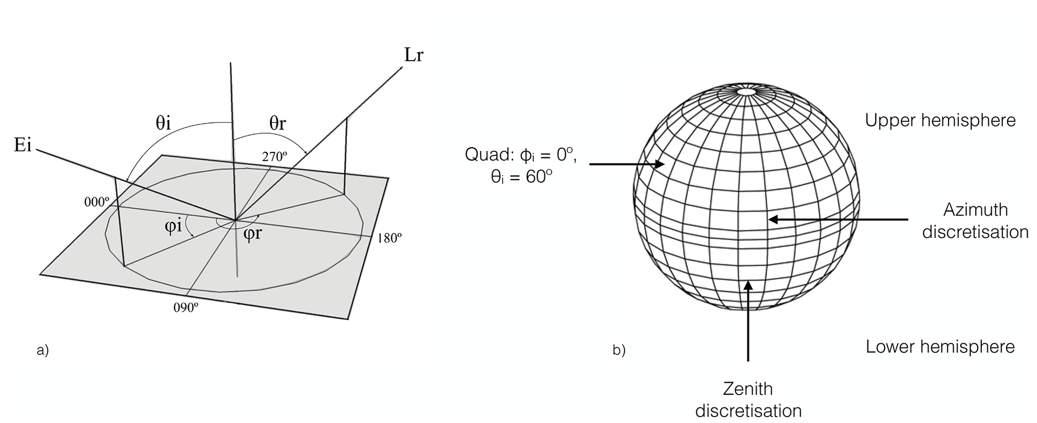
Figure 1(a) Diagram of the incident and viewing configuration defining CCRF. Ei is the irradiance from the azimuth angle ϕi and the zenith angle θi. Lr is the radiance in the azimuth angle ϕr and zenith angle θr. In this study, ϕi was fixed to 180∘, with the model being rotationally invariant. (b) Diagram of the directional surface discretisation scheme used by PlanarRad to compute CCRF. Adapted from Hedley (2008).
The BRDF of an ideal Lambertian reflector is (Nicodemus et al., 1977; Schaepman-Strub et al., 2006). Hence, a BRDF may be converted to BRF by multiplying by π.
2.2 Model description
The calculations of the CCRF, as an alternative to BRDF, of sea ice were performed using PlanarRad (Hedley, 2015), a radiative-transfer model that computes the radiance distributions and derived quantities for homogeneous scattering and absorbing media (Hedley, 2008). The model is an open-source implementation of the invariant imbedded numerical integration technique for radiative transfer, based on the algorithm described by Mobley (1994). PlanarRad has previously been used for reflectance computations in marine environments (Lim et al., 2009; Hedley et al., 2012) and is functionally similar to the commercial software HydroLight (Mobley, 1989).
In PlanarRad, radiance is calculated as the average radiance over finite solid angles, defined by a discretisation of the surface of a sphere divided into two hemispheres (Fig. 1b). The lower hemisphere corresponds to the upwelling radiance (exiting the surface), whereas the upper hemisphere corresponds to the downwelling direct sky radiance. The discretisation is determined by bounding lines of constant zenith (θ) and azimuth (ϕ) angles, forming quadrangular regions, commonly called “quads”. The two hemispheres are divided into 9 by 24 segments each, forming a total of 432 quads over the whole sphere. The directionally averaged radiance is computed by PlanarRad within each quad. The input irradiance is set to a single quad with a fixed azimuth, ϕi, and a variable zenith, θi, with the model being rotationally invariant. Radiance is constant over the solid angle subtended by each segment of the angular discretisation, both for upwelling and downwelling radiation, and the directional reflectance is evaluated as conical–conical or biconical (geometry equivalent to case 5 in Table 2 of Schaepman-Strub et al., 2006). For the rough surface constructed from randomly oriented surfaces used in this study, only the relative azimuth angle between ϕi and ϕr is required. The incident irradiance was fixed at a constant value for the purpose of this study. The azimuth angles corresponding to the quad centres are located every 15∘ from to , and the zenith angles corresponding to the quad centres are located at and 87.5∘. Out of convention, the incident azimuth angle, ϕi, was set to 180∘; the quarter sphere from 270 to 90∘ azimuth, representing the forward scattering of photons; and the quarter sphere from 90 to 270∘ azimuth, representing the backward scattering. Thus, the solar principal plane is defined as ϕ=180–0∘. Figure 2 shows a typical 2D polar plot of a PlanarRad output for optically thick (as described in Sect. 2.4) first-year sea ice, with a solar zenith angle of and a roughness parameter of σ=0.01 (described below).
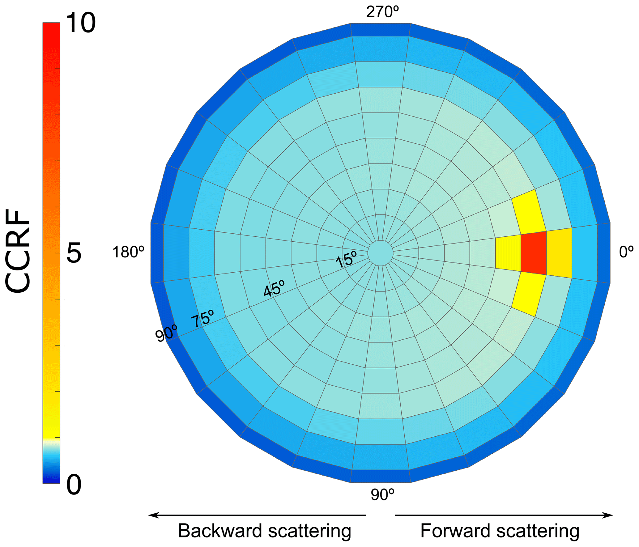
Figure 2Polar plot of the CCRF of optically thick first-year sea ice, with a solar zenith angle of and a roughness parameter of σ=0.01. The solar azimuth angle ϕi is located at 180∘; consequently, the left half of the hemisphere between and represents the backward-scattering component, and the right half of the hemisphere between and represents the forward-scattering component. In this case, a strong specular forward-scattering peak can be observed centred over the quad located at and . A nonlinear colour bar was used to capture the large values around the scattering peak whilst showing the pattern in the quasi-isotropic part of the CCRF.
The absorption coefficient (a), attenuation coefficient (α), scattering phase function, complex refractive index of sea ice, complex refractive index outside the sea ice, surface roughness and thickness of the sea ice were used in the radiative-transfer calculations. The parameters are presented in Sect. 2.4. The calculations presented here assume that no atmosphere is present and that the sea ice is floating on an optically thick body of seawater that has a wavelength-independent diffuse reflectance of 0.1.
2.3 Roughness parameter
A roughness parameter affecting the statistical distribution of surface slope was implemented in a similar way to that described in Mobley (1994). The roughness parameter, σ, describes the standard deviation of the height relative to the horizontal distance and is therefore unitless. For example, if σ=0.5, two points located 2 mm apart would have their heights drawn from a normal distribution of mean zero and standard deviation of 1 mm. As the system is considered spatially consistent, the overall CCRF and the effect of σ is scale invariant. The surface was modelled as a grid of equilateral triangles, and the height of the vertices was set randomly using σ. The procedure is the same as the one applied to water surfaces in Mobley (1994), except there σ is derived from wind speed and the triangles are not equilateral to account for directional dependency of water waves. The transfer of photons across the realised surfaces was modelled using Monte Carlo ray tracing over the discretised sphere described previously. In the work presented here, five modelled surfaces were generated with an elevation standard deviation σ equal to 0.001, 0.005, 0.01, 0.05, and 0.1 and visualised in Fig. 3. The surfaces were generated using 10 rays per quad (4320 rays in total), with results averaged over 2000 surfaces. With the roughness model being scale invariant and the relative amplitude defined as 1 m, the scale height of the roughness is 0.1, 0.5, 1, 5 and 10 cm.
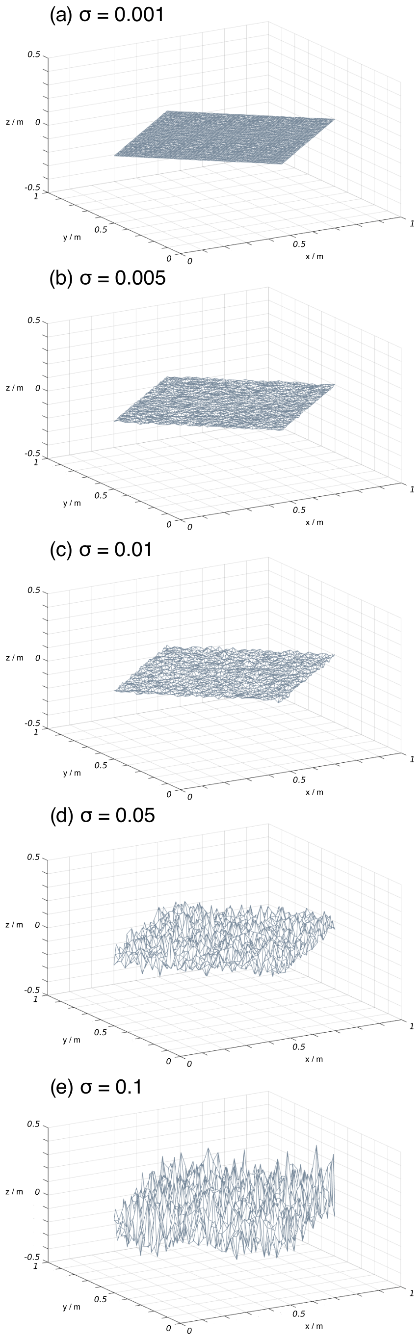
Figure 3Visualisation of example random surface roughness input parameters, controlled by the standard deviation (σ) of the elevation of the surface. In this study, five surface roughnesses of (a) σ=0.001, (b) σ=0.005, (c) σ=0.01, (d) σ=0.05 and (e) σ=0.1 were generated.
To cover a wide range of conditions, a selection of five surface roughness parameters defined by the standard deviation of the height of the surface were picked, with a standard deviation of 1 mm to 10 cm relative to two surface points 1 m horizontally apart. The range of surface roughness is in agreement with observations reported in the literature for small-scale roughnesses (e.g. Tucker et al., 2013).
Random surface realisations were generated to calculate the surface roughness in the model, which is rotationally invariant, Fig. 3. Therefore, PlanarRad produces a random surface roughness that has no specific structure or pattern. Specific complicated shapes present in sea ice, such as pressure ridges, were not modelled.
2.4 Calculation of the CCRF of three types of sea ice with different roughness parameters
The CCRF of three types of sea ice were modelled: first-year ice, multi-year ice and melting ice. The selected optical and physical parameters were based on field studies and cover a wide range of observed values (Lamare et al., 2016; Marks and King, 2014, 2013). A base amount of black carbon was added to the model to be more representative of natural sea ice, as small quantities of black carbon deposited from the atmosphere in polar regions (e.g Doherty et al., 2010) are likely to be found in sea ice. The mass absorption coefficient of black carbon was calculated using Mie theory, using refractive indices from Chang and Charalampopoulos (1990) and following the method described by Flanner et al. (2007). A mass ratio of 1 ng g−1 of black carbon was added to the sea ice by combining the mass absorption coefficients of sea ice and black carbon. The attenuation coefficient of sea ice was calculated using the scattering cross sections and densities described by Lamare et al. (2016) and Marks and King (2014) as
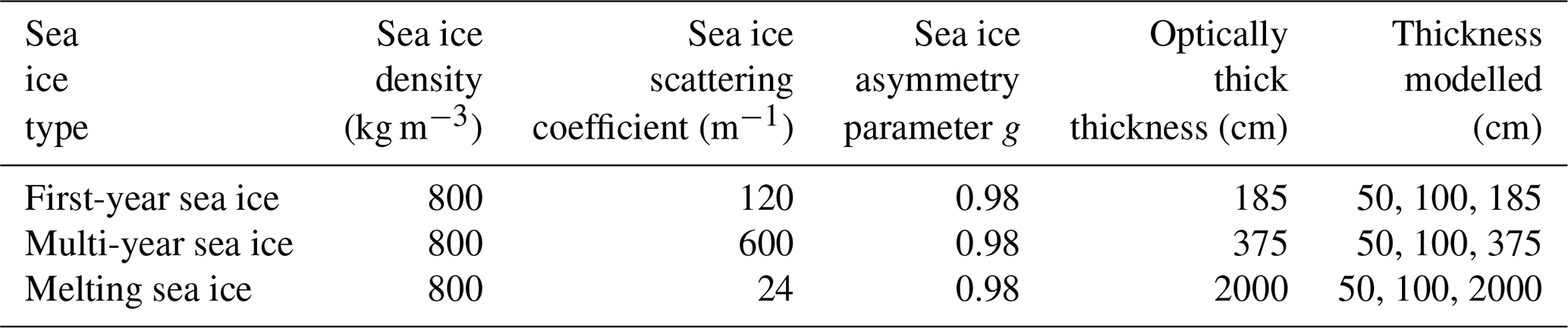
where α is the attenuation coefficient of sea ice, a is the absorption coefficient of sea ice with an added mass ratio of 1 ng g−1 of black carbon, s is the scattering coefficient of sea ice, ϕs is the scattering cross section and σs is the density. According to Light et al. (2004), the fractional volume of ice is larger than the fractional volume of brine, and the absorption coefficient of ice is similar to the absorption coefficient of brine; hence, the absorption coefficient of sea ice may be set equivalent to pure ice. Therefore, the refractive index of pure ice (Warren and Brandt, 2008) was used for sea ice, and a refractive index value of 1.0 was used above sea ice. To describe the directionality of the scattering of the sea ice, the Henyey–Greenstein phase function (Henyey and Greenstein, 1941) was used, with a fixed, wavelength-independent asymmetry factor g of 0.98 (Lamare et al., 2016). In this work, the asymmetry parameter, g, and the attenuation coefficient, a, were held constant, and the scattering coefficient, s, was varied to simulate different sea ice configurations, according to the methods outlined in Lee-Taylor and Madronich (2002). The optical and physical parameters of the selected sea ice types are summarised in Table 1. The scattering coefficient was fixed with wavelength (Malinka et al., 2018; Lamare et al., 2016).
Table 1Sea ice parameters used as input parameters for the PlanarRad model, based on literature values and detailed in the work of Lamare et al. (2016).
The CCRFs of the three different types of sea ice were subjected to solar radiation with a wavelength from 300 to 1400 nm with a 100 nm interval, as a function of surface roughness and ice thickness. The solar zenith angle was varied in 10 steps corresponding to the centre of the quads, from θi = 0∘ to , and the surface roughness parameterisations described in Sect. 2.2 were used, providing a wide range of configurations.
In some of the experiments described here, the sea ice is defined as optically thick to allow for a direct comparison between the different types of ice and with studies present in the literature. Optically thick sea ice as defined in this study is sea ice with a thickness for which the underlying medium (i.e. seawater) does not affect the surface reflectance. Previously, sea ice was considered to be optically thick at three e-folding depths, i.e. where over 95 % of diffuse incident radiation is attenuated (France et al., 2011). In the work described here, five e-folding depths, i.e. where over 99 % of diffuse incident radiation is attenuated, were used as a conservative approach because unlike previous studies – Lamare et al. (2016), Marks and King (2014), Marks and King (2013), and Redmond Roche and King (2022) – the study described here was using direct and not diffuse radiation. King et al. (2005) demonstrate that the decay of direct illumination in the near-surface region of sea ice is not asymptotic. Optically deep thicknesses of 1.85 m for first-year sea ice, 3.75 m for multi-year sea ice and 20 m for melting sea ice were picked, based on values compiled by Lamare et al. (2016). In a second step, sea ice thicknesses of 50 and 100 cm were selected for the three different types of sea ice. The two thicknesses were chosen to examine and inter-compare the effect of the sea ice thickness and roughness on the CCRF of different sea ice types rather than model representative values. Nevertheless, the model can produce results for a range of thicknesses, from the centimetre scale to optically thick thicknesses.
3.1 The variation of CCRF with roughness and sea ice thickness
The nadir CCRF of first-year sea ice, multi-year sea ice and melting sea ice with thicknesses of 50 100 cm and the optically thick thicknesses are shown in Fig. 4. The plotted data were obtained from the nadir quad of PlanarRad, with a surface roughness of σ=0.01 and a solar zenith angle of . The effect of the thickness of the sea ice on the nadir CCRF varies according to the type of sea ice. The nadir CCRF, at a wavelength of 500 nm, decreases by 21 % when going from an optically thick first-year sea ice to a 100 cm thick first-year sea ice and 47 % from optically thick to 50 cm. For multi-year ice the decrease in CCRF is 3 % from optically thick to 100 cm and 13 % from an optically thick thickness to 50 cm. Melting sea ice shows the largest change in nadir CCRF relative to thickness with a decrease in nadir CCRF of 73 % between an optically thick thickness and 100 cm and 84 % between an optically thick thickness and 50 cm. Melting sea ice is more translucent than first-year or multi-year sea ice; therefore, more photons penetrate the sea ice deeper and are absorbed by the underlying seawater, explaining the larger reduction in CCRF at nadir. On the contrary, with sea ice types that scatter photons more efficiently, fewer photons penetrate the ice deeply, and the proportion absorbed by the seawater under the ice is smaller.
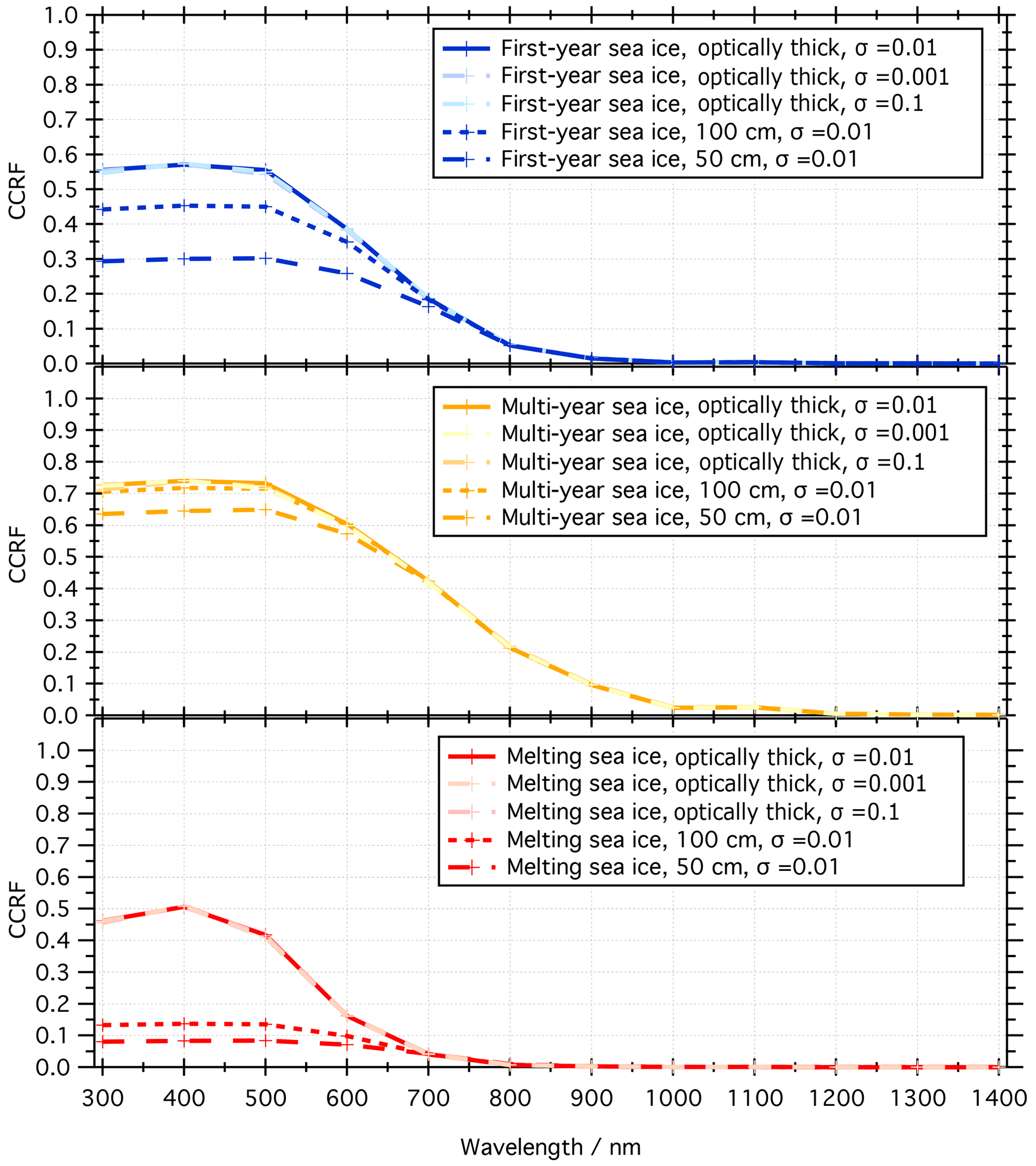
Figure 4Nadir CCRF for first-year, multi-year and melting sea ice, from 300 to 1400 in 100 nm steps with a solar zenith angle of and a roughness parameter of σ=0.01. The CCRF of the different types of sea ice is plotted for an optically thick layer (185, 375 and 2000 cm), 100 and 50 cm. For each optically thick layer of sea ice, the nadir CCRF is plotted for surface roughnesses of σ=0.001 and of σ=0.1. The different sea ice parameters defined in this study are reported in Table 1. The changes in nadir CCRF owing to changes in roughness are hard to discern, especially relative to changes in thickness.
To investigate the influence of surface roughness on the location of the dominant directional scattering of photons, hereafter referred to as the forward-scattering peak, the CCRF along the solar principal plane is presented. Knowledge of the intensity and size of the forward-scattering peak is essential to reliably calculate the energy budget of the sea ice and correct for the fluctuations in temporal remote sensing data (e.g. Leroy and Roujean, 1994; Li et al., 1996; Qu et al., 2016a; Zege et al., 2015). Figure 5 shows the effects of surface roughness on the forward-scattering peak of the CCRF of optically thick, first-year, sea ice with a solar zenith angle of . The results are also representative of multi-year and melting sea ice. Figure 5a displays the intensity, shape and position of the CCRF peak on the forward solar principal plane (). As the surface roughness increases, a spreading of the CCRF peak is observed. Indeed, the peak remains specular for the smaller surface roughnesses (σ=0.001 to σ=0.01), whereas for larger surface roughness features (above σ=0.05), the peak spreads out over multiple quads with a lower intensity than for smaller roughness features, and the highest value is displaced further out on the solar principal plane.
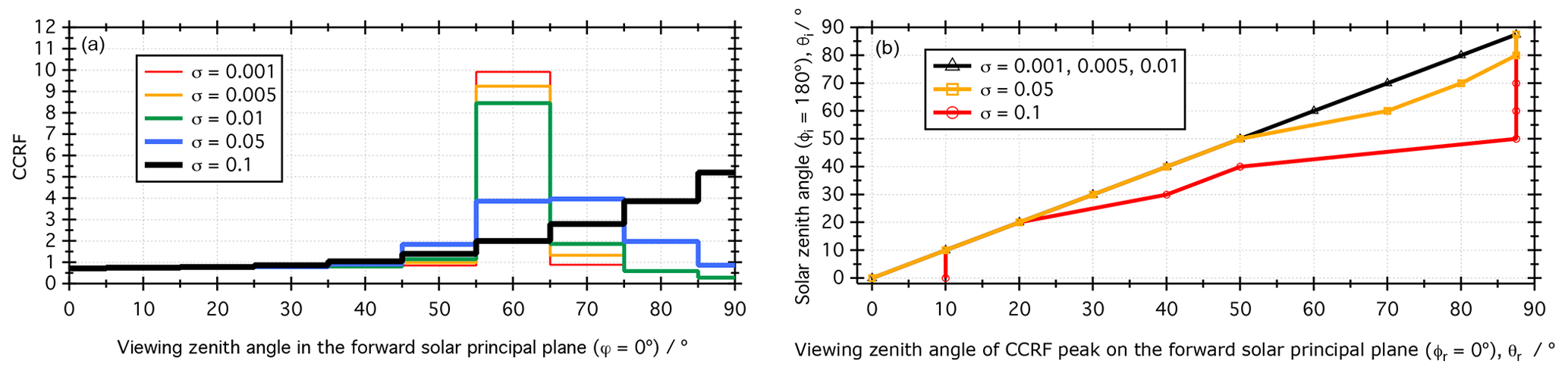
Figure 5The effects of roughness on the forward-scattering peak of the CCRF. (a) CCRF in the forward solar principal plane () of optically thick first-year sea ice, modelled with a solar zenith angle of as a function of surface roughness. (b) Location of the CCRF peak of optically thick first-year sea ice on the forward solar principal plane () as a function of solar zenith angle, θi, for different surface roughness parameters.
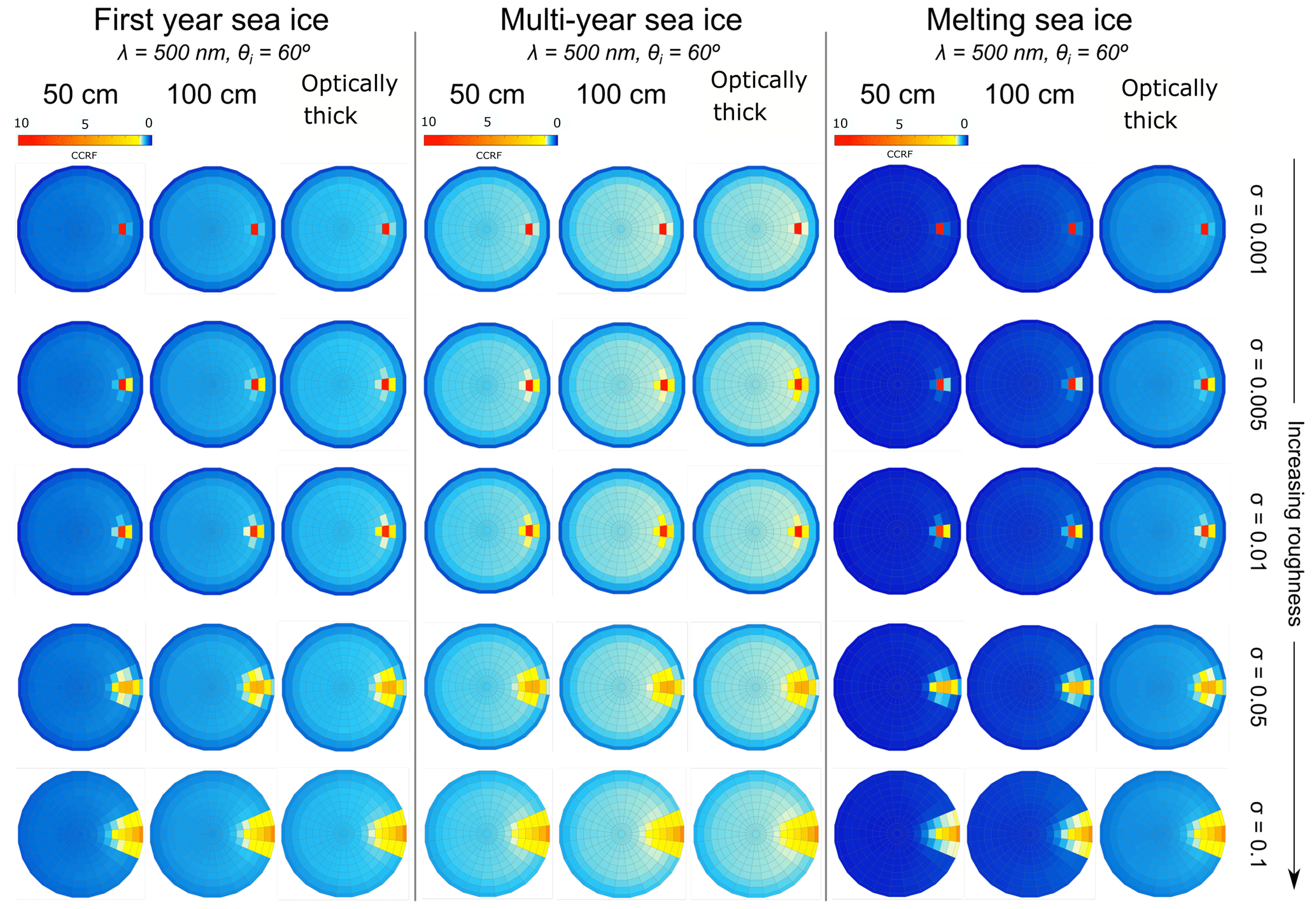
Figure 6CCRF of 50 cm, 100 cm and optically thick first-year sea ice, multi-year sea ice and melting sea ice with an increasing surface roughness. The incident angle is , and the results are reported for λ=500 nm.
Figure 6 shows the CCRF of first-year, multi-year and melting sea ice with a solar zenith angle of and at a wavelength of λ=500 nm. The CCRF was modelled for three thicknesses as a function of surface roughness: 50 cm, 100 cm and an optically thick layer. The modelled CCRF pattern is similar to snow (e.g. Dumont et al., 2010) and consistent with the literature for sea ice (e.g Arnold et al., 2002), showing a quasi-isotropic reflectance apart from a strong forward-scattering peak. The surface roughness plays an essential role in the CCRF of sea ice, by controlling the location and size of the forward-scattering peak, as shown previously in Fig. 5. Indeed, the peak is mostly specular and located in a single quad for a surface roughness of σ=0.001 and spreads out over multiple quads and moves to larger viewing zenith angle with a larger surface roughness. As a specific example, for first-year sea ice at λ=500 nm and , the CCRF of an optically thick layer with surface roughness of σ=0.001 is 0.543 at nadir. The forward-scattering peak is spread over a single quad located at , , that has a CCRF of 9.748. For the same configuration with surface roughness of σ=0.1, the nadir has a CCRF of 0.549 and the forward-scattering peak is spread over 18 quads, located between and , and , with values between 0.776 and 5.09. Furthermore, the effects of thickness and surface roughness on the CCRF of sea ice are inter-dependent. For smaller surface roughness parameters, an increase in the thickness of the sea ice mainly changes the intensity of the quasi-isotropic part of the CCRF, affecting the forward-scattering peak much less. For the first-year sea ice with the configuration described above and a roughness parameter of σ=0.001, the CCRF of the quad with the highest value in the specular peak increases by 2 % from a 50 cm layer to an optically thick layer, whereas the CCRF at nadir increases by 46 %. For larger surface roughnesses, a change in sea ice thickness affects the specular peak strongly, as well as the quasi-isotropic part of the CCRF. The CCRF of the first-year sea ice described previously with a surface roughness of σ=0.1 changes by 82 % at nadir and between 3 % and 69 % in the forward-scattering peak between a layer of 50 cm and an optically thick layer. Thus, the distribution and values of the CCRF over the azimuth, ϕ, and zenith, θ, are sensitive to the thickness and the roughness. For small roughnesses (σ<0.01) the quasi-isotropic part of the CCRF is affected by a changing thickness, and for large roughnesses (σ⩾0.01) the forward-scattering peak is also affected.
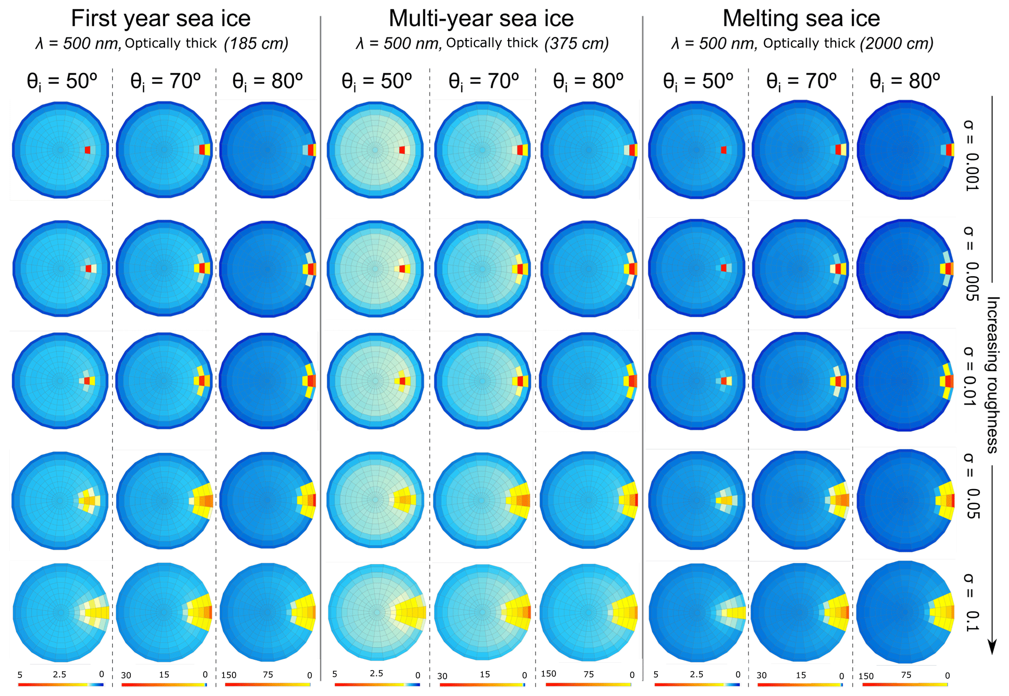
Figure 7CCRF of optically thick first-year sea ice, multi-year sea ice and melting sea ice with an increasing surface roughness at λ=500 nm. The incident angles are , and . Note that the scale of the colour bar varies for the different illumination angles in order to visualise clearly the BRF pattern.
3.2 The variation of CCRF with roughness and solar zenith angle
Figure 5b shows the effect of surface roughness on the position of the CCRF peak on the solar principal plane under different illumination conditions (θi=0 to 87.5∘). For the smaller roughness features (σ=0.001 to σ=0.01), the position of the peak on the solar principal plane is specular and therefore matches the solar zenith angle. A roughness of σ=0.05 affects the position of the CCRF peak at low sun angles (θi=60 to 87.5∘), moving the peak to a lower position on the hemisphere and therefore to a higher viewing zenith angle. For a solar zenith angle of , the viewing zenith angle is ; for , ; and for and 87.5∘, . With a surface roughness of σ=0.1, the forward-scattering peak is located at higher viewing zenith angles than the solar zenith angles, except for θi=10 and 20∘, where the angle of the forward-scattering peak equals the angle of incident illumination.
Figure 7 shows the CCRF of optically thick first-year, multi-year and melting sea ice at λ=500 nm, with an increasing surface roughness for three solar zenith angles, , and . Note that the scale of the colour bar varies for the different illumination angles in order to visualise clearly the CCRF pattern in Fig. 7. The results for can be found in Fig. 6 for comparison. Low illumination angles (large solar zenith angles) are presented in this study, as they are representative of conditions observable in polar regions. The location and intensity of the forward-scattering peak are strongly influenced by the incident zenith angle, whose effects are inter-dependent on surface roughness. For a small surface roughness of σ=0.001, the highest value of the forward-scattering peak is equal to the incident illumination angle over the range of solar zenith angles; however, the intensity of peak increases with θi. For first-year sea ice, the peak CCRF increases from 5.01 for to 28.9 for and to 143 for . The forward-scattering peak diffuses with larger solar zenith angles, from one quad at to three quads at for all three types of sea ice. With surface roughnesses of σ=0.005 and σ=0.01, the forward-scattering peak increases in intensity with increasing solar zenith angles; however, the peak remains spread over a similar number of quads between and . For larger surface roughnesses of σ=0.05 and σ=0.1, although the intensity of the wide forward-scattering peak increases with larger solar zenith angles, the intensity is lower than for small roughness parameters. For first-year sea ice with a surface roughness of σ=0.1, the highest CCRF value is 1.36 for and 54.3 for . Moreover, the forward-scattering peak is distributed over a larger number of quads for higher incident illumination angles. At large solar zenith angles, typical of polar latitudes, the isotropic part of the CCRF remains similar with an increasing surface roughness, whilst the forward-scattering peak diffuses and moves to larger viewing zenith angles than the incident illumination angles.
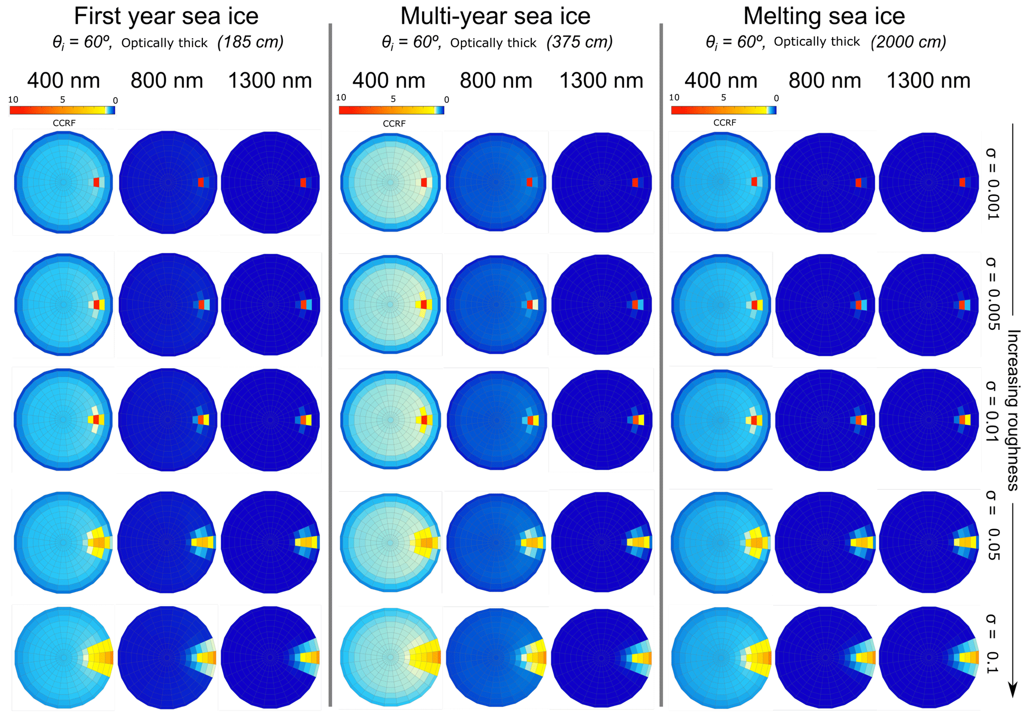
Figure 8CCRF of optically thick first-year sea ice, multi-year sea ice and melting sea ice with an increasing surface roughness for λ=400, λ=800 and λ=1300. The incident angle is .
3.3 The variation of CCRF with roughness and wavelength
For the three types of sea ice, the nadir value of the CCRF is strongly wavelength dependent due to the value of the absorption coefficient of ice increasing rapidly with wavelength and starting to change the interplay between scattering and absorption beyond 700 nm, as well as significantly lowering the CCRF. Although the different types of sea ice have a similar pattern with wavelength, the CCRF increases by 30 % from first-year sea ice to multi-year sea ice at 400 nm and up to 631 % at 1100 nm, 32 % from melting sea ice to multi-year sea ice at 400 nm and a maximum of 98 % at 900 nm, and 11 % from melting sea ice to first-year sea ice at 400 nm and up to 86 % at 800 nm.
However, the CCRF does not decrease uniformly over the hemisphere with an increasing wavelength. The CCRF of optically thick first-year sea ice, multi-year sea ice and melting sea ice with increasing surface roughness, for a solar zenith angle of and for wavelengths of λ=400 nm, 800 and 1300 nm, is shown in Fig. 8. The results for λ= 500 nm can be found in Fig. 6 for direct comparison. As partly shown in Fig. 4, the CCRF of sea ice is strongly wavelength dependent. At nadir, the highest CCRF values are found in the near-ultraviolet and visible wavelengths, decreasing rapidly between 500 and 900 nm. Beyond 900 nm for first-year and melting sea ice and 1000 nm for multi-year sea ice, the CCRF tends to zero, owing to the absorption by the sea ice. The quasi-isotropic part of the hemisphere follows the same trend as the nadir, whereas the forward-scattering peak conserves high CCRF values, independently of the wavelength. The behaviour is valid for the entire range of roughness parameters. For optically thick first-year sea ice with a solar zenith angle of , the nadir CCRF decreases by 99.92 % from 400 to 1300 nm for a surface roughness of σ= 0.001 and by 99.90 % for a surface roughness of σ=0.1. However, the change within the forward-scattering peak with wavelength differs for different amounts of surface roughness. For the same configuration with a surface roughness of σ=0.1, the wider forward-scattering peak decreases non-uniformly and reduces in size. Within the 18 quads of the forward-scattering peak located between and , and , the highest CCRF value () decreases by 15 %, but the lowest CCRF value () decreases by 83 % between 400 and 1300 nm. The same behaviour is observable for multi-year and melting sea ice. For small roughnesses (σ ⩽ 0.01) the intensity of the forward-scattering peak that does not change in size varies little with wavelength compared to the quasi-isotropic part of the CCRF. For large roughnesses (σ>0.01) the forward-scattering peak decreases strongly around the edges with wavelength, whereas the centre quads vary by a small amount as with smaller roughnesses. Furthermore, the quasi-isotropic part of the CCRF behaves in the same manner as for smaller surface roughnesses.
4.1 The effects of surface roughness on the CCRF of sea ice
As shown in Sect. 3, surface roughness plays a paramount role in the CCRF of bare sea ice. Not only does surface roughness have an effect on the reflected radiance, particularly in the forward-scattering peak, but it also modifies the behaviour of the CCRF with other controlling parameters such as thickness, solar zenith angle or wavelength. Surface roughness alone principally changes the specular forward-scattering peak by diffusing it around the specular point and outwards to a larger viewing zenith angle. Indeed, a smooth surface reflects the incident photons specularly, whereas reflection from a roughened surface is composed of the specular reflection of the angled facets in multiple directions as well as a diffuse component from the multiple reflections among the facets (Torrance and Sparrow, 1967). A reduction in thickness of a sea ice layer with a small amount of surface roughness mainly decreases the CCRF in the quasi-isotropic part, having little effect on the specular peak (Fig. 6). Indeed, with a thinner sea ice layer, a number of the scattered photons are absorbed by the strongly absorbing underlying layer (reflectance of 0.1) instead of exiting the medium upwards. Most of the photons scattered forwards exit the sea ice in the same manner as for an optically thick layer, explaining the smaller reduction in CCRF for the forward-scattering peak. When surface roughness is included, the forward-scattering peak is more sensitive to a changing thickness. With an increasing solar zenith angle, the CCRF with a smaller roughness parameter shows a decrease in intensity of the CCRF over the whole hemisphere apart from the specular peak that increases and moves in a specular manner relative to the solar zenith angle. With a higher solar zenith angle (lower sun on the horizon), the photons travel less deep into the sea ice than for a lower solar zenith angle and go through fewer scattering events due to the shorter path length and the relative angle between the incident path and the surface. Therefore, the photons are less scattered in multiple directions (lower CCRF over the hemisphere), and more photons are scattered forwards (stronger specular peak). However, increasing the surface roughness introduces more scattering events, as the photons are reflected at different angles off the features. Fewer photons travel directly in a specular manner, reducing the increase in the forward-scattering peak with an increasing solar zenith angle, and the larger number of scattering events leads to a smaller reduction in the CCRF of the remaining hemisphere.
Miao et al. (2020) also noted forward scattering of photons was strongly affected by “ice surface condition”. The directional reflectance of sea ice is strongly wavelength dependent owing to the photons scattering and absorption by the ice. At shorter wavelengths (300–900 nm), sea ice is highly scattering, whereas from 900–1400 nm the absorption by the ice dominates, with a nadir CCRF close to zero (Fig. 4). For a small amount of surface roughness, the CCRF exhibits the same wavelength dependence over the hemisphere, bar the specular peak (Fig. 8). Indeed, at longer wavelengths, the photons that are scattered in the sea ice are more likely to be absorbed than the photons quickly exiting the medium in a specular direction, creating a strong anisotropy. With increased surface roughness, a similar trend to the smaller surface roughness is observable; however, the size of the forward-scattering peak decreases with wavelength. The reduction may be caused by the absorption of photons at larger wavelengths that would otherwise have exited the ice in a forward direction after a low number of scattering events within the roughness features at lower wavelengths.
In the literature, a similar behaviour of the response of CCRF to an increasing roughness was observed by Jin and Simpson (1999), when modelling the anisotropic reflectance factor of sea ice with three different roughnesses. Jin and Simpson (1999) also modelled the effects of a varying solar zenith angle on the anisotropic reflectance factor of sea ice for a fixed roughness, showing that the reflectance anisotropy is much larger for a solar zenith angle of 60∘ than for 45∘. The effect of the solar zenith angle on the angular reflectance of sea ice was confirmed in the work presented here, additionally showing that surface roughness modulates the intensity and width of the forward-scattering peak. Arnold et al. (2002) presented an airborne case measurement of BRF for melt-season ice with a solar zenith angle of . Their measurement of BRF shows no significant departure from uniformity across the hemisphere, apart from a forward-scattering peak spread widely forward of the specular peak, suggesting large surface roughness. The BRF patterns reported in the principal plane for melt-season sea ice are in agreement with the modelled pattern of the CCRF presented here. However, the results from Arnold et al. (2002) are not directly comparable with the modelled CCRF, as the irradiance for the BRF measured with the Cloud Absorption Radiometer instrument is composed of a direct and a diffuse component, whereas the illumination in the modelling conducted here is direct only. Although not bare sea ice, there is some benefit in the comparison with the effect of surface roughness on the BRF of snow. Manninen et al. (2021) modelled the BRF of snow and found surface roughness of snow increased the backscattering at large solar zenith angle. Carlsen et al. (2020) measured the hemispherical directional reflectance factor (HDRF) of Antarctic snow surfaces in the 490–585 nm wavelength band using a 180∘ fisheye camera in an airborne platform whilst retrieving the surface roughness using an airborne laser scanner and found that the backscatter is enhanced over rougher surfaces, concluding that shadows and changing the effective angle of incidence were responsible. Accepting that snow and sea ice are different materials with some similar optical similarities, the findings presented here are consistent with the works of Manninen et al. (2021) and Carlsen et al. (2020).
4.2 Model limitations
As described in Sect. 2.2, PlanarRad computes the CCRF over a hemisphere discretised into quads, and the calculated radiance leaving the surface is averaged over each quad. The input irradiance was set to a single quad in this study. Therefore, the angular resolution of the model is limited to the quad size. Any differences in radiance within a single quad cannot be resolved, which results in a loss of definition for features smaller than the size of a single quad. Furthermore, in this configuration, the radiance for a quad containing the forward-scattering maxima is lower than the radiance of a specular peak if it is smaller than a quad. Ideally the solid angle of the illumination source, as well as the solid angle of the quads, should tend to zero. However, increasing the discretisation necessitates a considerable computational effort, which led the authors to the current choice of angular resolution representing a balance between resolution and computational resources. Computational time scales roughly as f3, where f is the angular resolution.
The radiative-transfer equation was computed without an atmosphere, providing a surface CCRF product, whereas the radiance measured by satellite sensors at the top of the atmosphere (TOA) is a function of the properties of the surface and the atmospheric conditions at the time of the measurement. The purpose of the study was to characterise and quantify the intrinsic CCRF of sea ice as a function of roughness and thickness that can be incorporated in radiative transfer models by the community. Therefore, to obtain a direct comparison with remote sensing products that have not been corrected for atmospheric effects, the results of this study have to be propagated to the TOA using an additional radiative-transfer model considering direct and diffuse illumination(e.g. Kotchenova et al., 2008).
In this study, the sea ice was modelled as a single homogeneous slab with defined optical properties. The model does not presently allow for the study of multiple layers with different optical properties. However, PlanarRad allows the input of a BRDF as a lower boundary condition; therefore, calculations for a layer of snow on the sea ice are possible. The work presented here focusses on a comprehensive characterisation of the CCRF of bare sea ice, which is lacking in the literature, and adding a layer of snow on the sea ice would have added too much complexity. Thus, snow was not considered in this study.
For the CCRF calculations described here, black carbon was assumed to be the only external absorber present in the ice. As described in Sect. 2.4, a base mass ratio of 1 ng g−1 was added to the modelled sea ice. Although organic debris, algae, soot, humic-like substances (HULIS) (Beine et al., 2012; France et al., 2012; Voisin et al., 2012) or mineral dust have an effect on the radiative forcing of sea ice, light-absorbing impurities other than black carbon were not examined in this study. Additionally, further investigation related to the effects of a varying mass ratio of light-absorbing impurities on the CCRF of sea ice is required.
The study presented here provides a large dataset parameterising the CCRF of bare sea ice, accounting for varying surface roughnesses. The CCRF of three different types of sea ice was modelled for a wavelength range of 300–1400 nm. The effects of surface roughness were investigated as a function of thickness, solar zenith angle and wavelength. Radiative-transfer calculations show that surface roughness has a significant effect on the CCRF of sea ice, controlling the anisotropy through the forward-scattering peak. Furthermore, the surface roughness is inter-dependent on other parameters that determine the CCRF pattern of sea ice, such as thickness, solar zenith angle and wavelength. As predicted by the model, the CCRF of sea ice exhibits a strong forward-scattering peak surrounded by a quasi-isotropic response. For small amounts of surface roughness, a reduction in sea ice thickness decreases the quasi-isotropic part of the CCRF, affecting the forward-scattering peak very little. The forward-scattering peak changes consistently in a specular manner with a varying solar zenith angle while the intensity of the peak increases. The forward-scattering peak is much less wavelength dependent than the surrounding quasi-isotropic part of the hemisphere. For larger amounts of surface roughness, a decrease in ice thickness affects strongly the entire CCRF, including the forward-scattering peak. The intensity of the forward-scattering peak increases and moves to larger viewing zenith angles than the solar zenith angles as the latter increase but remains overall lower than for smaller amounts of surface roughness. The size of forward-scattering peak is strongly wavelength dependent. As the surface roughness is inter-dependent on other physical parameters, it is essential to account for roughness in the theoretical calculations of the radiation budget of sea ice.
The study provides a wide range of CCRF for sea ice that covers the diversity of conditions encountered in nature. The data generated here are expected to facilitate the development of more accurate radiative-transfer models used to derive albedo products by the remote sensing community.
The code is available at http://www.planarrad.com (Hedley, 2015).
The data can be found at https://doi.org/10.5281/zenodo.5733402 (Lamare et al., 2021).
MLL performed the modelling, including the data analysis and result preparation, and authored the paper. JDH designed the model, wrote the roughness code and edited the paper. MDK conceived and oversaw the study and edited the paper.
The contact author has declared that none of the authors has any competing interests.
Publisher’s note: Copernicus Publications remains neutral with regard to jurisdictional claims in published maps and institutional affiliations.
This research has been supported by the Natural Environment Research Council (grant nos. NE/K000770X/1 and NE/T00732X/1).
This paper was edited by Tobias Bolch and reviewed by two anonymous referees.
Arnold, G. T., Tsay, S.-C., King, M. D., Li, J. Y., and Soulen, P. F.: Airborne spectral measurements of surface-atmosphere anisotropy for arctic sea ice and tundra, Int. J. Remote Sens., 23, 3763–3781, https://doi.org/10.1080/01431160110117373, 2002. a, b, c, d, e
Bacour, C., Bréon, F.-M., Gonzalez, L., Price, I., Muller, J.-P., and Straume, A. G.: Simulating Multi-Directional Narrowband Reflectance of the Earth's Surface Using ADAM (A Surface Reflectance Database for ESA's Earth Observation Missions), Remote Sens., 12, 1679–1703, https://doi.org/10.3390/rs12101679, 2020. a
Ball, C. P., Marks, A. A., Green, P. D., MacArthur, A., Maturilli, M., Fox, N. P., and King, M. D.: Hemispherical-Directional Reflectance (HDRF) of Windblown Snow-Covered Arctic Tundra at Large Solar Zenith Angles, IEEE T. Geosci. Remote, 53, 5377–5387, https://doi.org/10.1109/TGRS.2015.2421733, 2015. a
Becker, S., Ehrlich, A., Jäkel, E., Carlsen, T., Schäfer, M., and Wendisch, M.: Airborne measurements of directional reflectivity over the Arctic marginal sea ice zone, Atmos. Meas. Tech., 15, 2939–2953, https://doi.org/10.5194/amt-15-2939-2022, 2022. a
Beine, H., Anastasio, C., Domine, F., Douglas, T., Barret, M., France, J., King, M., Hall, S., and Ullmann, K.: Soluble chromophores in marine snow, seawater, sea ice and frost flowers near Barrow, Alaska, J. Geophys. Res.-Atmos., 117, D00R15, https://doi.org/10.1029/2011JD016650, 2012. a
Buckley, R. G. and Trodahl, H. J.: Scattering and absorption of visible light by sea ice, Nature, 326, 867–869, https://doi.org/10.1038/326867a0, 1987. a
Carlsen, T., Birnbaum, G., Ehrlich, A., Helm, V., Jäkel, E., Schäfer, M., and Wendisch, M.: Parameterizing anisotropic reflectance of snow surfaces from airborne digital camera observations in Antarctica, The Cryosphere, 14, 3959–3978, https://doi.org/10.5194/tc-14-3959-2020, 2020. a, b
Chang, H. and Charalampopoulos, T. T.: Determination of the Wavelength Dependence of Refractive Indices of Flame Soot, P. Roy. Soc. Lond. A Mat., 430, 577–591, https://doi.org/10.1098/rspa.1990.0107, 1990. a
Curry, J. A., Schramm, J. L., and Ebert, E. E.: Sea Ice-Albedo Climate Feedback Mechanism, J. Climate, 8, 240–247, https://doi.org/10.1175/1520-0442(1995)008<0240:SIACFM>2.0.CO;2, 1995. a
Doherty, S. J., Warren, S. G., Grenfell, T. C., Clarke, A. D., and Brandt, R. E.: Light-absorbing impurities in Arctic snow, Atmos. Chem. Phys., 10, 11647–11680, https://doi.org/10.5194/acp-10-11647-2010, 2010. a
Dumont, M., Brissaud, O., Picard, G., Schmitt, B., Gallet, J.-C., and Arnaud, Y.: High-accuracy measurements of snow Bidirectional Reflectance Distribution Function at visible and NIR wavelengths – comparison with modelling results, Atmos. Chem. Phys., 10, 2507–2520, https://doi.org/10.5194/acp-10-2507-2010, 2010. a
Flanner, M. G., Zender, C. S., Randerson, J. T., and Rasch, P. J.: Present-day climate forcing and response from black carbon in snow, J. Geophys. Res.-Atmos., 112, D11202, https://doi.org/10.1029/2006JD008003, 2007. a
Flanner, M. G., Shell, K. M., Barlage, M., Perovich, D. K., and Tschudi, M. A.: Radiative forcing and albedo feedback from the Northern Hemisphere cryosphere between 1979 and 2008, Nature Geosci., 4, 151–155, https://doi.org/10.1038/ngeo1062, 2011. a
France, J. L., King, M. D., Lee-Taylor, J., Beine, H. J., Ianniello, A., Domine, F., and MacArthur, A.: Calculations of in-snow NO2 and OH radical photochemical production and photolysis rates: A field and radiative-transfer study of the optical properties of Arctic (Ny-Ålesund, Svalbard) snow, J. Geophys. Res.-Earth, 116, F04013, https://doi.org/10.1029/2011JF002019, 2011. a
France, J. L., Reay, H. J., King, M. D., Voisin, D., Jacobi, H. W., Domine, F., Beine, H., Anastasio, C., MacArthur, A., and Lee-Taylor, J.: Hydroxyl radical and NOx production rates, black carbon concentrations and light-absorbing impurities in snow from field measurements of light penetration and nadir reflectivity of onshore and offshore coastal Alaskan snow, J. Geophys. Res.-Atmos., 117, D00R12, https://doi.org/10.1029/2011JD016639, 2012. a
Gatebe, C. K. and King, M. D.: Airborne spectral BRDF of various surface types (ocean, vegetation, snow, desert, wetlands, cloud decks, smoke layers) for remote sensing applications, Remote Sens. Environ., 179, 131–148, https://doi.org/10.1016/j.rse.2016.03.029, 2016. a, b
Goyens, C., Marty, S., Leymarie, E., Antoine, D., Babin, M., and Bélanger, S.: High Angular Resolution Measurements of the Anisotropy of Reflectance of Sea Ice and Snow, Earth and Space Science, 5, 30–47, https://doi.org/10.1002/2017EA000332, 2018. a
Hedley, J.: A three-dimensional radiative transfer model for shallow water environments, Opt. Express, 16, 21887–21902, https://doi.org/10.1364/OE.16.021887, 2008. a, b, c
Hedley, J.: PlanaRad, http://www.planarrad.com, last access: 1 January 2015. a, b, c
Hedley, J. D., Roelfsema, C. M., Phinn, S. R., and Mumby, P. J.: Environmental and Sensor Limitations in Optical Remote Sensing of Coral Reefs: Implications for Monitoring and Sensor Design, Remote Sens., 4, 271, https://doi.org/10.3390/rs4010271, 2012. a
Henyey, L. G. and Greenstein, J. L.: Diffuse radiation in the Galaxy, Astrophys. J., 93, 70–83, https://doi.org/10.1086/144246, 1941. a
Hudson, S. R., Kato, S., and Warren, S. G.: Evaluating CERES angular distribution models for snow using surface reflectance observations from the East Antarctic Plateau, J. Geophys. Res.-Atmos., 115, D03101, https://doi.org/10.1029/2009JD012624, 2010. a
Jin, Z. and Simpson, J.: Bidirectional anisotropic reflectance of snow and sea ice in AVHRR Channel 1 and 2 spectral regions. I. Theoretical analysis, IEEE T. Geosci. Remote, 37, 543–554, https://doi.org/10.1109/36.739110, 1999. a, b, c, d, e, f, g
King, M., France, J., Fisher, F., and Beine, H.: Measurement and modelling of UV radiation penetration and photolysis rates of nitrate and hydrogen peroxide in Antarctic sea ice: An estimate of the production rate of hydroxyl radicals in first-year sea ice, J. Photoch. Photobio. A, 176, 39–49, https://doi.org/10.1016/j.jphotochem.2005.08.032, 2005. a
Kotchenova, S. Y., Vermote, E. F., Levy, R., and Lyapustin, A.: Radiative transfer codes for atmospheric correction and aerosol retrieval: intercomparison study, Appl. Opt., 47, 2215–2226, 2008. a
Lamare, M. L., Lee-Taylor, J., and King, M. D.: The impact of atmospheric mineral aerosol deposition on the albedo of snow & sea ice: are snow and sea ice optical properties more important than mineral aerosol optical properties?, Atmos. Chem. Phys., 16, 843–860, https://doi.org/10.5194/acp-16-843-2016, 2016. a, b, c, d, e, f, g
Lamare, M., Hedley, J., and King, M.: The effects of surface roughness on the spectral (300–1400 nm) bidirectional reflectance distribution function (BRDF) of sea ice, Zenodo [data set], https://doi.org/10.5281/zenodo.5733402, 2021. a
Lee-Taylor, J. and Madronich, S.: Calculation of actinic fluxes with a coupled atmosphere–snow radiative transfer model, J. Geophys. Res.-Atmos., 107, ACH 22-1–ACH 22-10, https://doi.org/10.1029/2002JD002084, 2002. a
Leroy, M. and Roujean, J. L.: Sun and view angle corrections on reflectances derived from NOAA/AVHRR data, IEEE T. Geosci. Remote, 32, 684–697, https://doi.org/10.1109/36.297985, 1994. a
Li, S. and Zhou, X.: Modelling and measuring the spectral bidirectional reflectance factor of snow-covered sea ice: an intercomparison study, Hydrol. Process., 18, 3559–3581, 2004. a
Li, Z., Cihlar, J., Zheng, X., Moreau, L., and Ly, H.: The bidirectional effects of AVHRR measurements over boreal regions, IEEE T. Geosi. Remote, 34, 1308–1322, https://doi.org/10.1109/36.544556, 1996. a
Light, B., Maykut, G. A., and Grenfell, T. C.: A temperature-dependent, structural-optical model of first-year sea ice, J. Geophys. Res.-Oceans, 109, C06013, https://doi.org/10.1029/2003JC002164, 2004. a
Lim, A., Hedley, J. D., LeDrew, E., Mumby, P. J., and Roelfsema, C.: The effects of ecologically determined spatial complexity on the classification accuracy of simulated coral reef images, Remote Sens. Environ., 113, 965–978, https://doi.org/10.1016/j.rse.2009.01.011, 2009. a
Malinka, A., Zege, E., Istomina, L., Heygster, G., Spreen, G., Perovich, D., and Polashenski, C.: Reflective properties of melt ponds on sea ice, The Cryosphere, 12, 1921–1937, https://doi.org/10.5194/tc-12-1921-2018, 2018. a
Manninen, A. T.: Surface roughness of Baltic sea ice, J. Geophys. Res.-Oceans, 102, 1119–1139, https://doi.org/10.1029/96JC02991, 1997. a
Manninen, T., Anttila, K., Jääskeläinen, E., Riihelä, A., Peltoniemi, J., Räisänen, P., Lahtinen, P., Siljamo, N., Thölix, L., Meinander, O., Kontu, A., Suokanerva, H., Pirazzini, R., Suomalainen, J., Hakala, T., Kaasalainen, S., Kaartinen, H., Kukko, A., Hautecoeur, O., and Roujean, J.-L.: Effect of small-scale snow surface roughness on snow albedo and reflectance, The Cryosphere, 15, 793–820, https://doi.org/10.5194/tc-15-793-2021, 2021. a, b
Marks, A. A. and King, M. D.: The effects of additional black carbon on the albedo of Arctic sea ice: variation with sea ice type and snow cover, The Cryosphere, 7, 1193–1204, https://doi.org/10.5194/tc-7-1193-2013, 2013. a, b, c
Marks, A. A. and King, M. D.: The effect of snow/sea ice type on the response of albedo and light penetration depth (e-folding depth) to increasing black carbon, The Cryosphere, 8, 1625–1638, https://doi.org/10.5194/tc-8-1625-2014, 2014. a, b, c
Miao, Y., Peng, L., Xiao-wei, C., Ming-guang, T., Qing-kai, W., and Zhi-jun, L.: Field Observations of the Bidirectional Reflectance Characteristics of Lake Ice, Spectrosc. Spect. Anal., 40, 2453–2461, 2020. a
Mishchenko, M. I., Dlugach, J. M., Yanovitskij, E. G., and Zakharova, N. T.: Bidirectional reflectance of flat, optically thick particulate layers: an efficient radiative transfer solution and applications to snow and soil surfaces, 18, 3559–3581, J. Quant. Spectrosc. Ra., 1999. a
Mobley, C. D.: A numerical model for the computation of radiance distributions in natural waters with wind-roughened surfaces, Limnol. Oceanogr., 34, 1473–1483, https://doi.org/10.4319/lo.1989.34.8.1473, 1989. a
Mobley, C. D.: Light and Water: Radiative Transfer in Natural Waters, Academic Press, ISBN-10 0125027508, 1994. a, b, c
Nicodemus, F. E., Richmond, J. C., Hsia, J. J., Ginsberg, I. W., and Limperis, T.: Geometrical Considerations and Nomenclature for Reflectance, NBS MN-160, library pc congress cat no. 77-22966, National Beareau of Standards monograph 160, 1977. a, b, c, d, e
Perovich, D. K.: The Optical Properties of Sea Ice., Monograph 96-1, U. S. Cold Reg. Res. and Eng. Lab., 1996. a, b
Perovich, D. K., Grenfell, T. C., Light, B., and Hobbs, P. V.: Seasonal evolution of the albedo of multiyear Arctic sea ice, J. Geophys. Res.-Oceans, 107, 8044, https://doi.org/10.1029/2000JC000438, 8044, 2002. a
Peterson, I. K., Prinsenberg, S. J., and Holladay, J. S.: Observations of sea ice thickness, surface roughness and ice motion in Amundsen Gulf, J. Geophys. Res.-Oceans, 113, C060016, https://doi.org/10.1029/2007JC004456, 2008. a
Qu, X. and Hall, A.: Surface Contribution to Planetary Albedo Variability in Cryosphere Regions, J. Climate, 18, 5239–5252, https://doi.org/10.1175/JCLI3555.1, 2005. a
Qu, Y., Liang, S., Liu, Q., He, T., Liu, S., and Li, X.: Mapping Surface Broadband Albedo from Satellite Observations: A Review of Literatures on Algorithms and Products, Remote Sens., 7, 990–1020, https://doi.org/10.3390/rs70100990, 2015. a
Qu, Y., Liang, S., Liu, Q., Li, X., Feng, Y., and Liu, S.: Estimating Arctic sea-ice shortwave albedo from MODIS data, Remote Sens. Environ., 186, 32–46, https://doi.org/10.1016/j.rse.2016.08.015, 2016a. a
Qu, Y., Liang, S., Liu, Q., Li, X., Feng, Y., and Liu, S.: Estimating Arctic sea-ice shortwave albedo from MODIS data, Remote Sens. Environ., 186, 32–46, https://doi.org/10.1016/j.rse.2016.08.015, 2016b. a
Redmond Roche, B. H. and King, M. D.: Quantifying the effects of background concentrations of crude oil pollution on sea ice albedo, The Cryosphere, 16, 3949–3970, https://doi.org/10.5194/tc-16-3949-2022, 2022. a
Schaepman-Strub, G., Schaepman, M., Painter, T., Dangel, S., and Martonchik, J.: Reflectance quantities in optical remote sensing – definitions and case studies, Remote Sens. Environ., 103, 27–42, https://doi.org/10.1016/j.rse.2006.03.002, 2006. a, b, c, d, e, f
Schlosser, E.: Optical studies of Antarctic sea ice, Cold Reg. Sci. Technol., 15, 289–293, https://doi.org/10.1016/0165-232X(88)90075-4, 1988. a
Stamnes, K., Hamre, B., Stamnes, J., Ryzhikov, G., Biryulina, M., Mahoney, R., Hauss, B., and Sei, A.: Modeling of radiation transport in coupled atmosphere-snow-ice-ocean systems, J. Quant. Spectrosc. Ra., 112, 714–726, https://doi.org/10.1016/j.jqsrt.2010.06.006, 2011. a, b
Torrance, K. E. and Sparrow, E. M.: Theory for Off-Specular Reflection From Roughened Surfaces, J. Opt. Soc. Am., 57, 1105–1114, https://doi.org/10.1364/JOSA.57.001105, 1967. a
Tucker, W. B., Perovich, D. K., Gow, A. J., Weeks, W. F., and Drinkwater, M. R.: Physical Properties of Sea Ice Relevant to Remote Sensing, 9–28, American Geophysical Union, https://doi.org/10.1029/GM068p0009, 2013. a, b
Voisin, D., Jaffrezo, J.-L., Houdier, S., Barret, M., Cozic, J., King, M. D., France, J. L., Reay, H. J., Grannas, A., Kos, G., Ariya, P. A., Beine, H. J., and Domine, F.: Carbonaceous species and humic like substances (HULIS) in Arctic snowpack during OASIS field campaign in Barrow, J. Geophys. Res.-Atmos., 117, D00R19, https://doi.org/10.1029/2011JD016612, 2012. a
Warren, S. G. and Brandt, R. E.: Optical constants of ice from the ultraviolet to the microwave: A revised compilation, J. Geophys. Res.-Atmos., 113, D14220, https://doi.org/10.1029/2007JD009744, 2008. a
Warren, S. G., Brandt, R. E., and O'Rawe Hinton, P.: Effect of surface roughness on bidirectional reflectance of Antarctic snow, J. Geophys. Res.-Planet., 103, 25789–25807, https://doi.org/10.1029/98JE01898, 1998. a
Weeks, W. F. and Ackley, S. F.: Growth conditions and the structure and properties of sea ice, in: Physics of Ice Covered Seas: An Advanced Study Institute-Summer School, Springer, https://doi.org/10.1007/978-1-4899-5352-0_2, 1994. a
Zege, E., Malinka, A., Katsev, I., Prikhach, A., Heygster, G., Istomina, L., Birnbaum, G., and Schwarz, P.: Algorithm to retrieve the melt pond fraction and the spectral albedo of Arctic summer ice from satellite optical data, Remote Sens. Environ., 163, 153–164, https://doi.org/10.1016/j.rse.2015.03.012, 2015. a