the Creative Commons Attribution 4.0 License.
the Creative Commons Attribution 4.0 License.
 | 08 Apr 2022
A new Stefan equation to characterize the evolution of thermokarst lake and talik geometry
Benjamin M. Jones
Andrew D. Parsekian
Kenneth M. Hinkel
Katsu Yamatani
Mikhail Kanevskiy
Rodrigo C. Rangel
Amy L. Breen
Helena Bergstedt
Thermokarst lake dynamics, which play an essential role in carbon release due to permafrost thaw, are affected by various geomorphological processes. In this study, we derive a three-dimensional (3D) Stefan equation to characterize talik geometry under a hypothetical thermokarst lake in the continuous permafrost region. Using the Euler equation in the calculus of variations, the lower bounds of the talik were determined as an extremum of the functional describing the phase boundary area with a fixed total talik volume. We demonstrate that the semi-ellipsoid geometry of the talik is optimal for minimizing the total permafrost thaw under the lake for a given annual heat supply. The model predicting ellipsoidal talik geometry was compared to talik thickness observations using transient electromagnetic (TEM) soundings in Peatball Lake on the Arctic Coastal Plain (ACP) of northern Alaska. The depth : width ratio of the elliptical sub-lake talik can characterize the energy flux anisotropy in the permafrost, although the lake bathymetry cross section may not be elliptic due to the presence of near-surface ice-rich permafrost. This theory suggests that talik development deepens lakes and results in more uniform horizontal lake expansion around the perimeter of the lakes, while wind-induced waves and currents are likely responsible for the elongation and orientation of shallow thermokarst lakes without taliks in certain regions such as the ACP of northern Alaska.
- Article
(10289 KB) - Full-text XML
- BibTeX
- EndNote


Thermokarst lakes are abundant in regions underlain by ice-rich permafrost including the Arctic Coastal Plain (ACP) of northern Alaska, northwestern Canada, and Siberia (Grosse et al., 2013; Jones et al., 2022). These lakes are formed due to permafrost degradation, and their basin evolution is fundamentally different from lakes formed in temperate and tropical regions. Thermokarst lakes affect the thermal regime of the surrounding permafrost, which controls the geomorphology and evolution of the lake basin (Brewer, 1958). If the lake bed has a mean annual temperature greater than 0 ∘C, the sub-lake permafrost will begin to thaw (Burn, 2002; Arp et al., 2016). This typically occurs in lakes that are deeper than the maximum winter ice thickness, where the ice cover floats above an unfrozen water layer (Jeffries et al., 1996; Burn, 2002). In this case, unfrozen lake bed sediments persist, and the thaw front continues to penetrate deeper into the underlying permafrost. This results in a “talik”, or a perpetually unfrozen zone confined by permafrost, beneath the lake depending on local anomalies in thermal, hydrological, hydrogeological, or hydrochemical conditions (van Everdingen, 1998). In ice-rich permafrost, the conversion of ice to water with thaw causes a volumetric reduction in the unconsolidated material, and the lake bed consequently subsides significantly, increasing the depth of initial basins (Czudek and Demek, 1970; Jorgenson and Shur, 2007; Shur and Osterkamp, 2007; Jorgenson, 2013; French, 2018). The total depth of thaw subsidence is determined by the amount and distribution of excess ice content in the permafrost with depth. As the lake expands by lateral thermomechanical erosion of the banks, mineral and organic sediments from retreating shores are delivered to the lake basin (Farquharson et al., 2016). However, thaw-induced ground subsidence effectively deepens the basin, so volumetric capacity can increase over time. Over decades and centuries, the talik increases in thickness, and lake bed subsidence continues as long as the thawing permafrost is ice-rich (West and Plug, 2008).
In certain ice-rich permafrost regions in the Arctic, there is a preferential orientation and elliptic shape to the thermokarst lakes (Black and Barksdale, 1949; Hinkel et al., 2005; Grosse et al., 2013). In particular, elliptical-oriented lake districts are found predominantly along the central north Siberian coast, northern Alaska, and in northwest Canada (Grosse et al., 2013). On the ACP of northern Alaska, many elliptical thermokarst lakes have a long axis oriented 10–20∘ W from true north, which is nearly perpendicular to the prevailing wind direction (Carson, 1968; Sellmann, 1975; Carter, 1981). Hinkel et al. (2005, 2012) also showed significant correlation between lake orientation and summer wind direction by analyzing the geometric shape metrics of the thermokarst lakes and drained thermokarst lake basins (DTLBs) on the ACP of Alaska. It has been proposed that winds at the lake surface cause currents and water waves, which trigger thermomechanical bank erosion, resulting in asymmetrical elliptical orientation (Livingstone, 1954; Rex, 1961; Carson and Hussey, 1962; Mackay, 1992; Arp et al., 2011). The sublittoral shelves and bars typically found in the deeper thermokarst lakes may also be formed by wind-driven currents and waves, as well as warmer water temperatures (Carson and Hussey, 1962). The axis-oriented sublittoral shelves make the orientation appear more pronounced in larger basins. Other processes also influence the orientation of thermokarst lakes such as historical drained lake geometry, ground ice distribution, and dune ridge orientation by aeolian sand transport (Carter, 1981).
Several numerical models have been proposed and applied that describe permafrost thaw for the purpose of analyzing water and carbon cycles (e.g., Kessler et al., 2012). However, Schuur et al. (2015) stress the need to better represent talik formation and geometries to parameterize numerical models more effectively. Painter et al. (2016) demonstrated a coupled surface–subsurface permafrost thermal hydrology model at the multiple ice-wedge polygon scale. Kessler et al. (2012) simulated carbon mobilization over 10 000 years on two neighboring thaw lakes located on ice- and organic-rich Yedoma permafrost terrain (Kanevskiy et al., 2011; Schirrmeister et al., 2013) in the northern Seward Peninsula, Alaska, using a three-dimensional (3D) numerical thermal model. They demonstrated the effectiveness of model simulations for methane emission from thermokarst lakes. Ling and Zhang (2003b) provided a numerical parametrization of lake talik development and showed that shallow thermokarst lakes are a significant heat source affecting permafrost and talik geometries. Rowland et al. (2011) advanced the technique by including advective heat transport on talik evolution. West and Plug (2008) and Plug and West (2009) characterized the lake bathymetry including the effects of lake ice and littoral shelves. These thermal models use long-term mean lake temperature as the Dirichlet boundary condition and a uniform annual mean temperature profile as the initial condition. Analytical and numerical models can provide dynamic solutions for the heat transfer equation under quasi-steady-state climate conditions. However, the existing models require prescribed lake shapes (circle or ellipse) to obtain information on talik depths as opposed to modeling the likely influence of talik evolution on lake shape – this work, in part, attempts to address this shortcoming.
Direct drilling measurements of taliks below thermokarst lakes are difficult to obtain and only exist in a few rare case studies (Brewer, 1958; Johnston and Brown, 1966; Roy-Leveilee and Burn, 2017; Heslop et al., 2015). Geophysical methods can be used (e.g., Schwamborn et al., 2000; Parsekian et al., 2019; Creighton et al., 2018; Sullivan et al., 2021; O'Neill et al., 2020); however, it is time consuming and laborious to produce 3D subsurface images at the large scale of lakes found in permafrost lowland regions. Since field measurements (coring, geophysics, etc.) are spatiotemporally limited, numerical and analytical modeling is used to gain critical insights into talik evolution. Mackay (1962) obtained the analytical vertical temperature profiles below the water at the center of a circular lake by analytically solving the heat transfer equation. Burn (2002) subsequently extended the solution for an elongated lake. This analytical model has been used for lake process characterization because the quasi-steady-state model was able to reasonably quantify the talik thickness. For example, Hinkel and Arp (2015) applied the temperature profile to 2100 lakes and found that larger, long-lived lakes (more than 66 ha) may have taliks that penetrate through the permafrost (open taliks) to the groundwater system below in a region with permafrost that is up to 600 m thick.
These existing models require the prescribed lake shapes (circle or ellipse) to obtain the talik depth; in fact, no existing studies explicitly provide an answer to the following fundamental question: why do thermokarst lakes tend to be elliptical and/or round? Also, in spite of several decades of research focused on the orientation of thermokarst lakes in certain regions, no existing studies explicitly explain why thermokarst lakes in some regions orient perpendicular to the prevailing wind direction. The objective of this work is to implement a novel mathematical framework that concurrently describes both the oriented nature of the thermokarst lakes and the talik depth below the lakes. Previous models have calculated the talik development due to heat flow, though most use some simplifying assumptions to reduce dimensionality. Separately, researchers have hypothesized about elliptical lake morphology by invoking winds, currents, and erosion. Here, we couple both the talik evolution and lake shape questions together in a single mathematical model. Additionally, we intend to use this theory to demonstrate that the thermal gradient could exert control on the depth : width ratio of the talik. In other words, the proposed theory aims to isolate the most important process – sub-lake permafrost thaw and subsidence – from other effects such as wind wave erosion, thaw slumping, sediment redistribution and incoming radiation imbalance, using thermally optimized lake geometry.
2.1 Basin-integrated energy equation
The approach used in this study is based on Lagrangian mechanics, which generalizes the classical Newtonian mechanics, using the stationary action principle (the principle of least action). The action is defined as the integral of the Lagrangian, which consists of kinetic and potential energy of the system. In this application, the Lagrangian simply becomes the potential energy due to the absence of kinetic energy. The variational principle that is the main tool in Lagrangian mechanics can indeed derive the equations in Newtonian mechanics. One of the related research topics using the variational principle to fluid mechanics is phase boundary propagation, which can be analyzed by the phase field model or diffusion interface model (Cassel, 2013). This model explains the diffuse phase boundary without surface tension that appears in Newtonian interfacial physics between a liquid and a gas. According to the second law of thermodynamics, the free energy of the system must decrease monotonically to ensure a non-negative entropy production (Singer-Loginova and Singer, 2008). This requires that the time rate of change in the phase boundary be expressed by the functional derivative of the free energy functional, which corresponds to the total energy flux into the talik in relation to permafrost thaw. This study directly and analytically solves the Euler–Lagrange equation based on the stationary action principle rather than the entropy functional used in the phase field method.
Heat energy collected by a waterbody is used for phase boundary expansion, as well as heat conduction into the adjacent permafrost (e.g., French, 2018). From the energy balance equation around the phase boundary, the energy for permafrost thaw is expressed as the subtraction of heat conduction from the input energy at the phase boundary (Carslaw and Jaeger, 1959; Patel, 1968; Lunardini, 1981). The material of permafrost and talik is assumed to be fully saturated with ice and water, respectively. Also, the thermal constants (thermal conductivity, latent heat, and thawing temperature) are constant and isotropic, and the change in volume of water on thawing and freezing is negligible. Under such assumptions, the energy conservation equation at the phase boundary can be expressed as
where ϕ is volumetric water content (m3 m−3), v is thaw rate or advancement of talik boundary (m s−1), ρ is density of water (kg m−3), L is latent heat for ice thaw (liquid–solid) (J kg−1), qsuf is additional heat input from ground surface around the lakeshore (W m−2), kL is thermal conductivity of unfrozen soil (W (m ∘C)−1), kp is thermal conductivity of frozen soil (permafrost) (W (m ∘C)−1), T is temperature (∘C), and n is outward normal from the interface into the soil (m). The energy terms can be grouped into heat for permafrost thaw qth (W m−2), incoming heat at the phase boundary qin (W m−2), and outgoing heat by conduction to the permafrost qout (W m−2). These heat fluxes can be evaluated by the following formulas:
When heat input from the surface is consumed for phase change without any loss (, the well-known Stefan equation can be obtained from Eqs. (1) through (4) under the quasi-steady-state approximation (Stefan, 1891; Kurylyk and Hayashi, 2016). This study also adopts the quasi-steady-state approximation for the talik shape characterization.
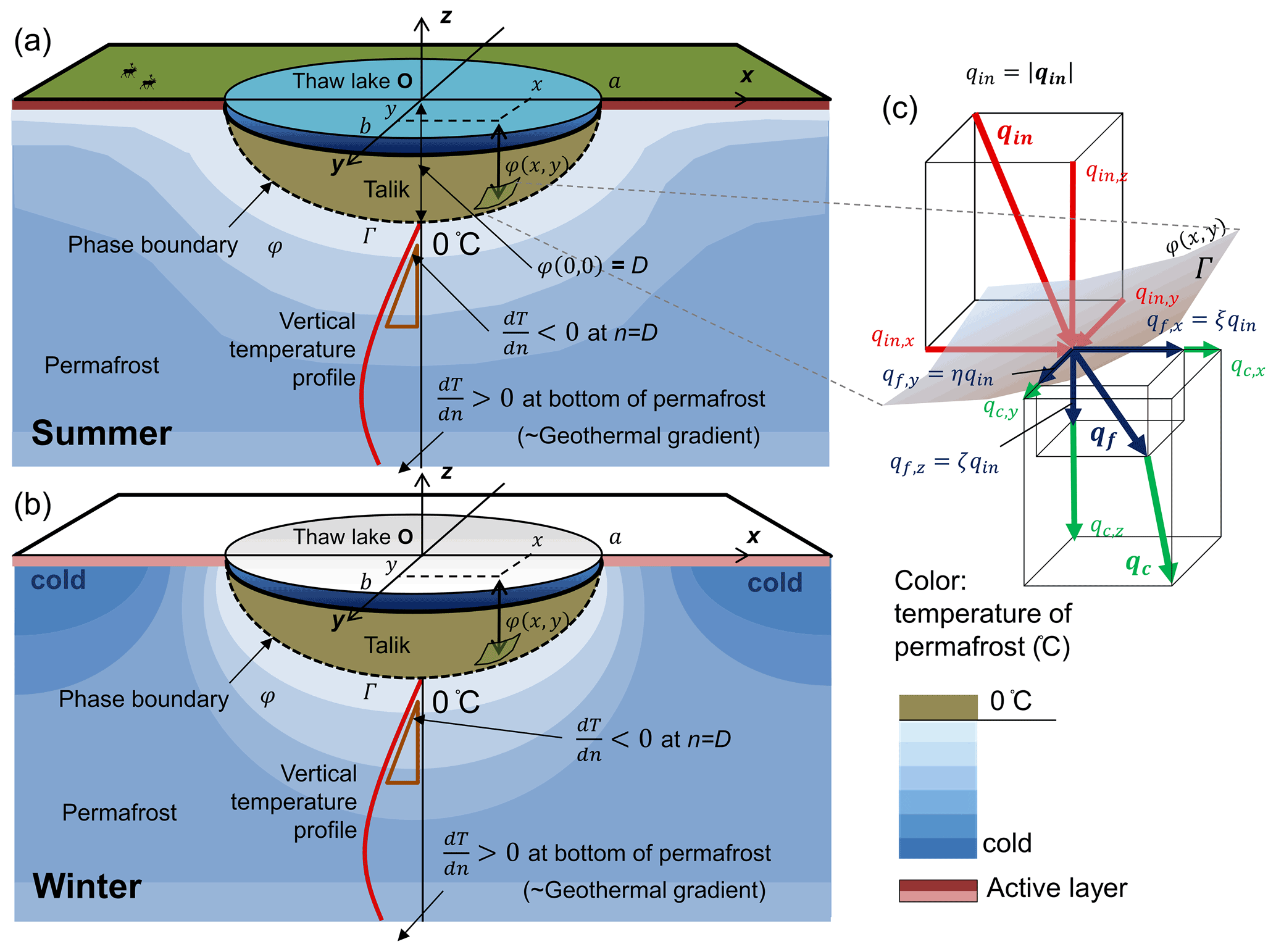
Figure 1Definitions of variables associated with the overall shape of phase boundary φ during warm (a) and cold seasons (b) and incoming and outgoing heat transfers on φ(x,y) (c). Incoming heat (red-colored vector) is perpendicular to the phase boundary φ(x,y), while thaw direction (blue-colored vector) is modified by the anisotropic heat conduction (green-colored vector) in the permafrost.
As the thawing process is direction-dependent, it is convenient to use vector notation (Fig. 1). That is,
A vector is denoted by a bold and italic letter. The talik expansion flux vector corresponds to thaw direction, which is affected by the other two heat fluxes. Figure 1 illustrates the thermal profiles around the thaw lake in warm and cold seasons. The horizontal near-surface heat conduction is influenced by the seasonality of the surface heat budget, while the vertical heat conduction under the lake remains unidirectional throughout the years. Clearly, the presence of the thaw lake considerably alters the heat environment of the permafrost, while the temperature slope at the bottom of the permafrost may be approximated by the geothermal gradient in regions with thick continuous permafrost such as the ACP. This directionality in the heat environment around the lake may cause anisotropic talik expansion. Here, the phase change heat vector is expressed as being proportional to the normal heat input qin as follows:
where qin is the input heat normal to the phase boundary, and ξ,η, and ζ are the thaw energy fractions of the heat input normal to the phase boundary with respect to x, y, and z directions, respectively. The depth of the phase boundary (m), , may be expressed as an arbitrary 3D surface as
Hence, the normal vector n at any location on the phase boundary g can be written as follows:
where the subscript in this expression denotes partial derivative (e.g., ), and ∇ is a vector differential operator ). As such, the vector of the input heat to the phase boundary φ is
and the corresponding thaw heat vector is
Next, the thaw heat magnitude can be evaluated using a Euclidian norm as
where
The parameters αx and αy (unitless ratio) describe the anisotropic thermal condition between horizontal and vertical directions. The parameters αx and αy are greater than 1 when the vertical temperature gradient is steeper than in the horizontal gradient. The total thaw energy over the lake can be computed by the area integral on the phase boundary Γ. That is,
This expression indicates that the heat required for lake expansion is proportional to the weighted phase boundary area with the weights αx and αy.
2.2 Optimum phase boundary shape
The calculus of variation, often referred to as a functional analysis, is the mathematical technique to find an extremum (minimum or maximum) of the system in terms of a function type instead of a variable (e.g., Courant and Hilbert, 1954; Gelfand and Fomin, 1963). Thermally optimum function types φ(x,y) of the phase boundary can be derived using this method. As presented in the previous section, the heat consumption rate for talik expansion is represented by the weighted phase boundary area, while the time-integrated heat supply is equivalent to the thawed permafrost volume. Assuming heat thaws the most susceptible region of the permafrost near the heat source first, the shape of a talik may minimize the total permafrost thaw with a given amount of incoming energy. In other words, as the free energy of the system must decrease monotonically to ensure a non-negative entropy production (the second law of thermodynamics), the optimum talik shape should minimize the phase boundary area for a specified talik volume. The weighted phase boundary area A and its volume V can be expressed as follows:
To obtain the optimum talik shape, the functional F is formulated using the method of Lagrange multipliers as
where λ is the Lagrange multiplier. The minimum of the functional F can be determined for λ<0 because both V and A are monotonic functions. Let
Equation (15) becomes
Note that this functional can be interpreted as the Lagrangian of the system. Therefore, to find the extremal phase-boundary shape φ that minimizes the functional F[φ], the Euler–Lagrange equation can be formulated as
Substituting Eqs. (16) to (18) yields
By analogy to the two-dimensional (2D) application in Ohara and Yamatani (2019), an ellipsoid is one of the solutions of Eq. (20) as follows:
Detailed alternative derivation using isoperimetric inequality is available in Appendix A. The coefficients d and λ can be determined by further variational analysis explained in Appendix B. As such, Eqs. (21) and (22) become
D is the talik center depth, and αx and αy are the cross-sectional aspect ratios. Hence, the semi-ellipsoidal geometry of the phase boundary (i.e., the boundary between the permafrost and talik) was explicitly derived as a thermally optimum shape based on the variational principle using the thermal quasi-steady-state approximation. This result is consistent with the existing numerical thermal models (Schwamborn et al., 2000; Plug and West, 2009; Ling and Zhang, 2003b; Kessler et al., 2012) which predicted nearly elliptic talik cross sections under thaw lakes in a continuous permafrost. As the Stefan equation describes the phase boundary depth (active layer depth or frost depth) under a uniform and flat landscape, the solution of the Euler–Lagrange equation (Eq. 23) is the 3D Stefan equation for the talik beneath a thermokarst lake.
2.3 Thermokarst lake bathymetry and phase boundary geometry
When top-down permafrost thaw dominates the process, the thermokarst lake bottom shape ψ(x,y) may be similar to the phase boundary shape, as illustrated in Fig. 2. However, the lake bathymetry can be related to the permafrost degradation rate rdeg (ratio; m m) defined as
where H and D denote the water depth and the talik thickness at the lake center, respectively. Dfrzn is the frozen soil thickness (m), and Dthaw is the corresponding thawed soil thickness depth (m), which is strongly dependent on the excess ground ice content; excess ice is defined as the volume of ice in the ground, which exceeds the total pore volume that the ground would have under natural unfrozen conditions (van Everdingen, 1998). Therefore, thaw settlement is typically computed from excess ice content and the thickness of the layer with excess ground ice. However, as the consolidation settlement effect, which is a function of void ratio and effective stress, may not be separated, we use the simple permafrost degradation rate (Eq. 25) in this study.

Figure 2Lake bathymetry models for a thermokarst lake and the talik underneath based on the quasi-steady state. (a) The lake bathymetry is proportional to the talik geometry with uniform ice distribution. (b) The lake bathymetry tends to have a flat bottom due to the widespread ice-rich layer near the surface.
If the permafrost degradation rate is uniform and constant throughout the basin (Fig. 2a: uniform permafrost), the lake bathymetry tends to be an ellipsoid shape. However, as the ice-rich layer is typically developed near the surface on the ACP (e.g., Kanevskiy et al., 2011, 2013), the bathymetry may have a flatter bottom like a rectangular cross section (Fig. 2b: layered permafrost) because the ice-rich layer is characterized by much higher thaw settlement than the ice-poor permafrost at depth. Therefore, proportionality between talik thickness and lake water depth is unlikely a reasonable assumption due to the ice-rich layer presence. Indeed, Hinkel et al. (2012) showed many flat-bottomed lakes through the extensive bathymetry surveys across the ACP of Alaska using a GPS-enabled sonar from a boat.
Additionally, as hydrology also affects the lake water level, the apparent lake bathymetry, or lake water depth, h(x,y) must be adjusted by the water loss (or gain) per unit area. Therefore,
where Hloss (m) is the elevation difference between the current water surface and original ground surface before lake formation. At the lake center,
Thus, the thermokarst lake bathymetry is affected by the ice-rich layer thickness, interannual water balance, lake age, and talik geometry.
3.1 Study area
Peatball Lake ( N, W; 3 m above sea level) on the ACP of Alaska was chosen for the demonstrative model application in this study as it has been relatively well documented in previous studies (Lenz et al., 2016; Creighton et al., 2018; Parsekian et al., 2019). Figure 3 shows the location of Peatball Lake within the Teshekpuk Lake subregion, as well as other subregions that will be discussed later.
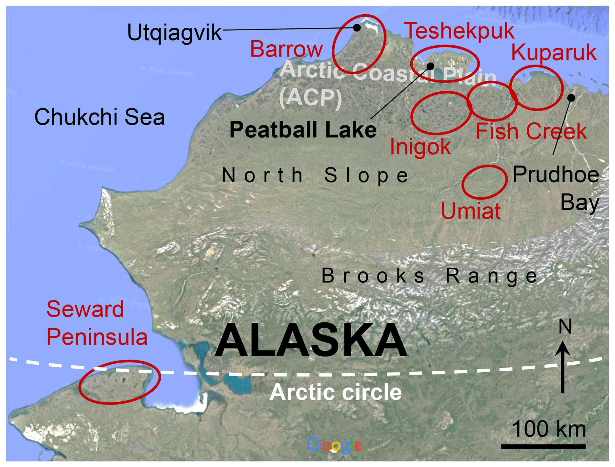
Figure 3Map of the study area: Peatball Lake and subregions for lake characterization (red).
Peatball Lake, named for the abundant submerged peat balls on the lake bed, is a subcircular lake on the Outer Coastal Plain of Alaska with a surface area of 1.18 km2. Permafrost in this area is as thick as ∼ 400 m (Jorgenson et al., 2008), and the average volumetric ground ice content is about 77 % in the near surface to a depth of 4 m (Kanevskiy et al., 2013). A talik has formed under Peatball Lake because the maximum water depth of 2.5 m exceeds the maximum winter ice thickness of 1.5 to 2.0 m (Arp et al., 2015; Lenz et al., 2016). The talik depth was estimated as 91 m at the lake center based on noninvasive transient electromagnetic (TEM) measurements (Creighton et al., 2018). However, the talik may not be present beneath the shallow sublittoral shelves on the western shore determined from the bathymetry (Lenz et al., 2016). Additionally, Lenz et al. (2016) reported that, based on remote sensing imagery, Peatball Lake has expanded laterally between 0.02 and 1.36 m yr−1 from 1955 to 2002.
3.2 Geophysical survey of talik
Geophysical field methods are effective for identifying and visualizing the frozen–unfrozen interface, which is a key feature in permafrost dynamics (e.g., Pilon et al., 1985; Doolittle et al., 1990; O'Neill et al., 2020; Rangel et al., 2021). For sub-lake taliks in the continuous permafrost zone, Schwamborn et al. (2000) analyzed the sedimentary history of Lake Nikolay in the western Lena River Delta using seismic reflection and ground penetrating radar (GPR). Other geophysical methods such as surface nuclear magnetic resonance (NMR) can be used to detect lake taliks (Parsekian et al., 2019) and remnant taliks in drained lake basins (Rangel et al., 2021). At Peatball Lake, Creighton et al. (2018) estimated the talik depth using transient electromagnetic (TEM) surveys along transects perpendicular to lakeshores. The dataset (Parsekian et al., 2018) at Peatball Lake is, to our knowledge, the only quasi-3D talik model available under an isolated lake in the continuous permafrost zone because others are mostly sporadic talik depth measurements at single drill points.
We applied the derived 3D Stefan equation to Peatball Lake based on 27 talik thickness point measurements across the lake (Fig. 4), estimated using TEM soundings (Creighton et al., 2018) during spring 2016 and 2017. Figure 4 shows the observed talik thicknesses by the TEM sounding (dots) and the fitted theoretical talik thickness estimates (contour lines) superimposed over the corresponding lake bathymetry measured by Lenz et al. (2016).
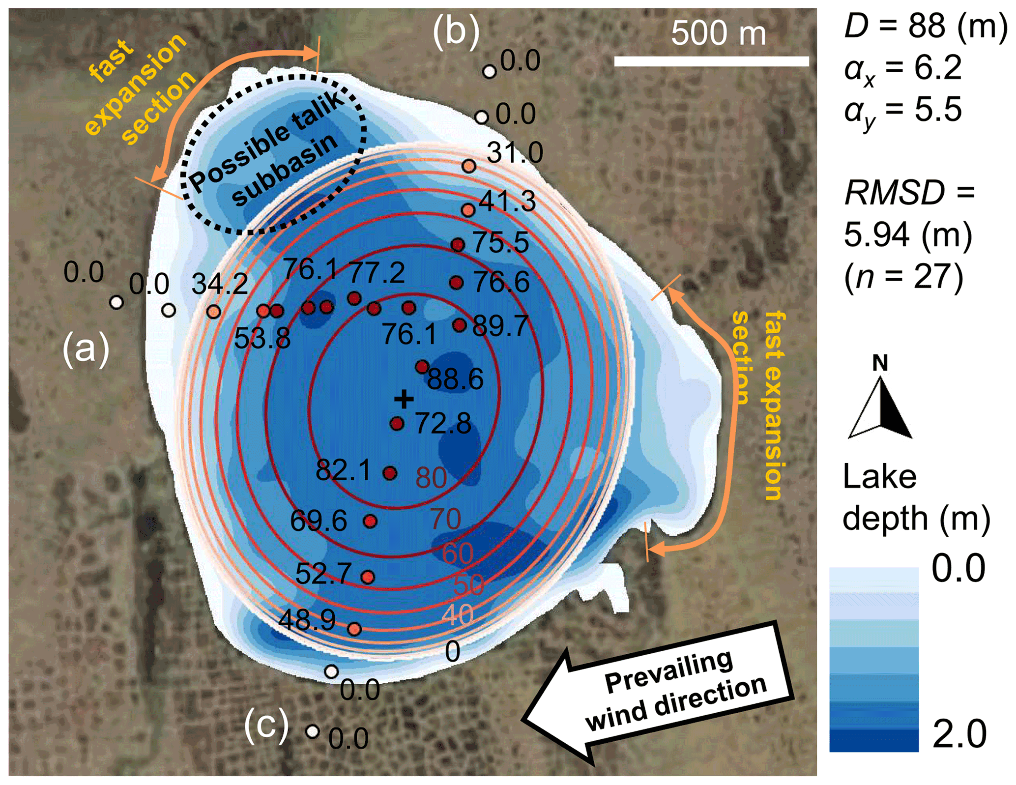
Figure 4The theoretically extrapolated talik thickness map (contour lines) based on 27 TEM soundings (dots) in Peatball Lake, ACP of Alaska. The red contour lines and the observation points are consistent. The corresponding observed lake bathymetry (adopted from Lenz et al., 2016) is also included in blue gradation. The TEM sounding transects start on the lakeshore and end near the center of the lake.
The geometric parameters of the semi-ellipsoid model such as the talik center depth (D), the cross-sectional aspect ratios (αx and αy), lake orientation azimuth angle, and the lake center location were systematically determined by grid searching to minimize the root mean square difference (RMSD) between the model and thaw front obtained from the TEM data. The optimum parameters for the smallest RMSD (5.94 m) are shown in Fig. 4. Unexpectedly, the basin orientation angle was found to be 23∘ E from true north, unlike the orientation of other surrounding lakes in the region. A comparison between the extrapolated talik geometry and the lake bathymetry (Lenz et al., 2016) suggests the possibility of the coalescence of two basins in the past, a relatively common occurrence on the ACP of Alaska. However, if we had more TEM measurement points, particularly in the “possible talik sub-basin”, the fitted talik geometry could be different as the model was only fitted for the 27 TEM soundings. Despite irregularity due to the complex lake formation history, the overall sub-lake talik geometry may be approximated by a semi-ellipsoidal shape as indicated by the very good fit of the elliptic model to the TEM-measured talik thicknesses (see Fig. 4 with overall RMSD = 5.94 m, 6.7 % of the maximum talik depth). The idealized, thermally optimum model geometry can partition talik irregularity associated with multi-generation lakes such as Peatball Lake.
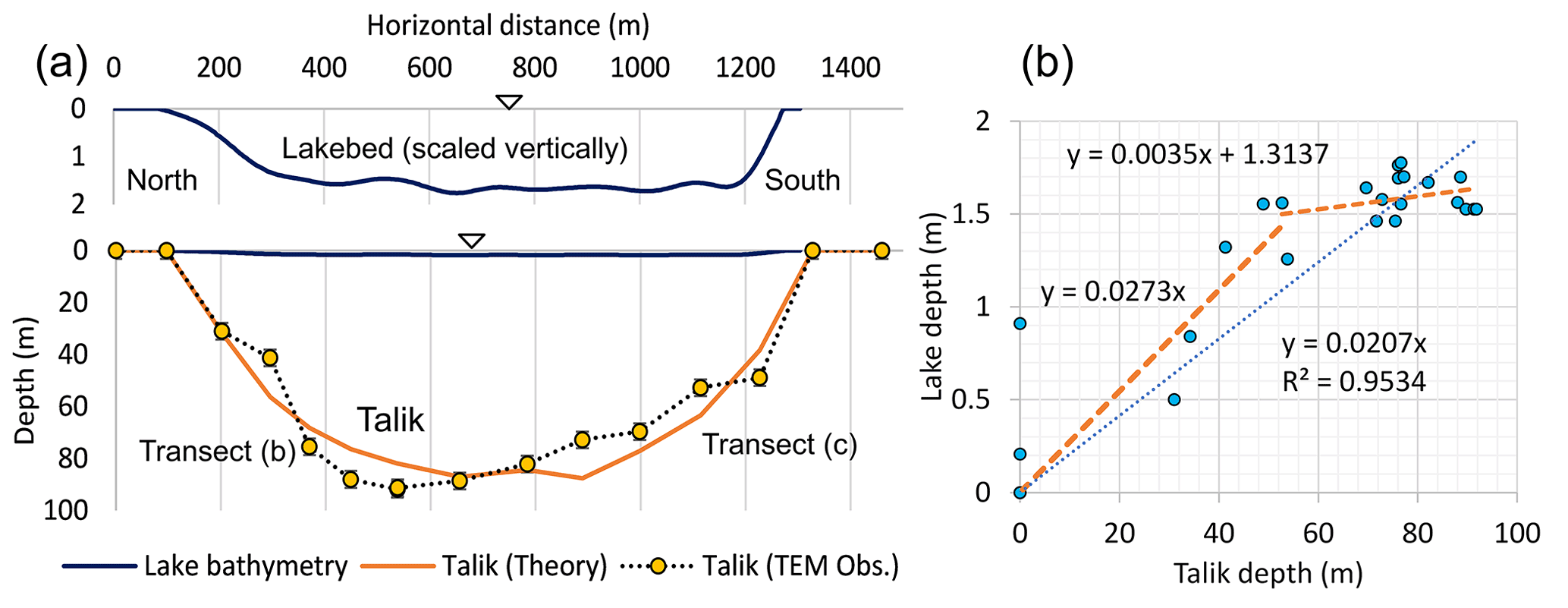
Figure 5(a) Cross-sectional comparisons of the lake bed and the talik profiles along the two TEM transects (b) through (c) (Lenz et al., 2016) in Peatball Lake. Panel (b) displays the cross plot of the observed talik and lake depths at all 27 TEM data points.
Additionally, the gaps between the shoreline and the modeled talik extent located along the north and east shores occur where lake expansion is most rapid (Lenz et al., 2016). It has been reported that thaw lake banks continuously retreat through a combination of thermal and mechanical processes, although there is significant variability in rate of bank retreat depending on the region (Hopkins, 1949; Hopkins et al., 1955; Tomirdiaro, 1982; Rampton, 1982; Burn and Smith, 1990; Jones et al., 2011; Lenz et al., 2016). Cross-sectional numerical thermal models demonstrated that the expansion rates are affected by the talik thickness (Plug and West, 2009) and seasonal snow cover (Ling and Zhang, 2003a). The disagreement between the lake and talik extents on the north and east shores of Peatball Lake implies that rapid horizontal lake expansion can locally dominate permafrost thaw and subsidence processes even in a lake with a talik.
Figure 5 compares the observed lake bed and talik profiles in Peatball Lake along the north–south center line and along the transects (b) and (c), respectively. Note that the TEM transects for the talik is not a straight line (See Fig. 4); therefore, the fitted theoretical line shows irregularity. Figure 5a illustrates that the lake bed profile is characterized by flatter trapezoidal geometry compared to the elliptic talik. In fact, there is a clear inflection in the linear regression line at a talik depth of ∼ 50 m in Fig. 5b. From the slopes of the regression lines, the permafrost degradation rates rdeg are computed as 97.3 % and 99.7 % for the shallow talik section (50 m or less) and the deep section (50 m or more), respectively. This analysis suggests that the subsidence due to permafrost thaw continues even after the shallow ice-rich part of the permafrost (about 4 m; Kanevskiy, 2013) is thawed, while it has diminished around the depth of 50 m under Peatball Lake. This case study demonstrates a link between lake bathymetry and talik thickness associated with a layered permafrost structure.
3.3 Depth : width ratio and temperature gradient
The analysis (Eqs. 23 and 24) suggests the proportional relationship between lake and talik geometry and thaw energy. That is,
Combining Eqs. (28), (1), and (4), the depth : width (radius) ratio of the talik may be written as follows:
where r and n are the horizontal and vertical distances from the original permafrost surface center, respectively, and a is the representative horizontal radius of the lake. This expression states that the anisotropic top-down permafrost thaw is caused by anisotropy of the thermal gradient for uniform incoming energy and uniform thermal properties of near-surface permafrost. For example, since the vertical thermal gradient is typically steeper than the horizontal gradient during the critical summer months (Carson and Hussey, 1962; illustration in Fig. 1), the heat energy in the vertical direction is used more for heat conduction rather than permafrost thawing. The vertical temperature gradient is always negative near the talik boundary in the permafrost at the center of the lake, while the inter-seasonal average of the horizontal thermal gradient may be negligible . As a result, lateral thaw is faster than vertical thaw due to less energy loss to horizontal heat conduction (McClymont et al., 2013; Devoie et al., 2021). Assuming the normal heat flux to the phase boundary is uniform throughout the phase boundary surface ), Eq. (29) can be simplified as follows:
This simple expression may be a useful tool to link the lake depth : width ratio, the lake average heat flux qin, and the vertical temperature gradient at the base of the talik. Since in the permafrost near the talik boundary, the is always less than 1 (flatter than a semi-sphere). However, the depth : width ratio of the talik depends on the vertical temperature slope near the talik boundary, which is likely affected by talik age. For instance, Mackay's analytical model (1962) suggests that the vertical temperature gradient below the lake center begins steeply at the talik initiation, and then over time it approaches a lower slope at equilibrium. Therefore, the formula in Eq. (30) suggests that a younger talik should be flatter, while an older talik approaches a deeper semi-spherical shape ().
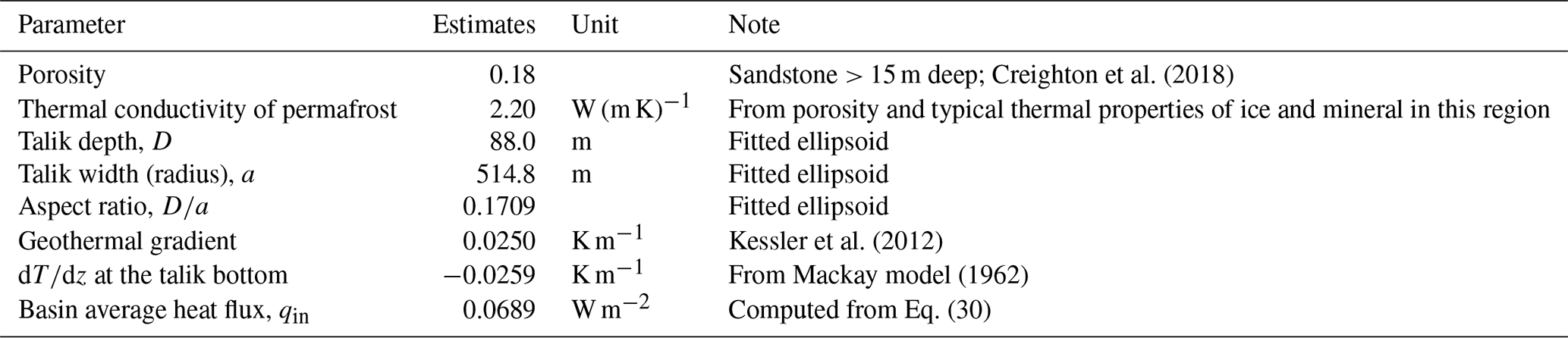
Table 1 shows the estimated incoming heat flux with the key parameters using the proposed formula (Eq. 30). Creighton et al. (2018) applied the CRYOGRID2 model (Westerman et al., 2013) to Peatball Lake. The temperature slope at the talik bottom at the lake center was estimated by Mackay's analytical model assuming the lake age of 1400 years since the talik initiation with the same model configuration that Creighton et al. (2018) adopted. Creighton et al. (2018) estimated the interannual mean heat flux qin to be 0.070 (W m−2), which is very close to our estimate. As this simplified formula is consistent with the well-configured modeling result, the horizontal thermal gradient contribution to the vertical aspect ratio of the talik seems to be very small in Peatball Lake.
Table 1Computed incoming heat flux with the estimated parameters.
Moreover, this relationship may be useful to incorporate the 3D talik expansion effect in a simple analysis without fully integrated permafrost thermal modeling. For example, if the mean energy flux increases 10 % from current climate conditions (e.g., shorter lake freeze period), assuming all other properties and horizontal thermal gradient variation remain unchanged, the talik depth : width ratio would shift from 0.171 to 0.234 toward the new equilibrium state. Therefore, this analysis suggests that a warmer climate may promote permafrost thaw in the vertical direction more than in the horizontal direction. Hence, it is important to quantify the vertical thawing, as well as the visible lake horizontal expansion, in order to evaluate the impact of the climate change on permafrost thaw beneath thermokarst lakes.
4.1 Relationship between hypothetical models
To illustrate the applicability of the thermal model presented here, the available hypothetical models of thermokarst lake growth are compiled in Fig. 6. This diagram focuses on the physical processes after the lake initiation stage assuming the bio-ecological effects are negligible.
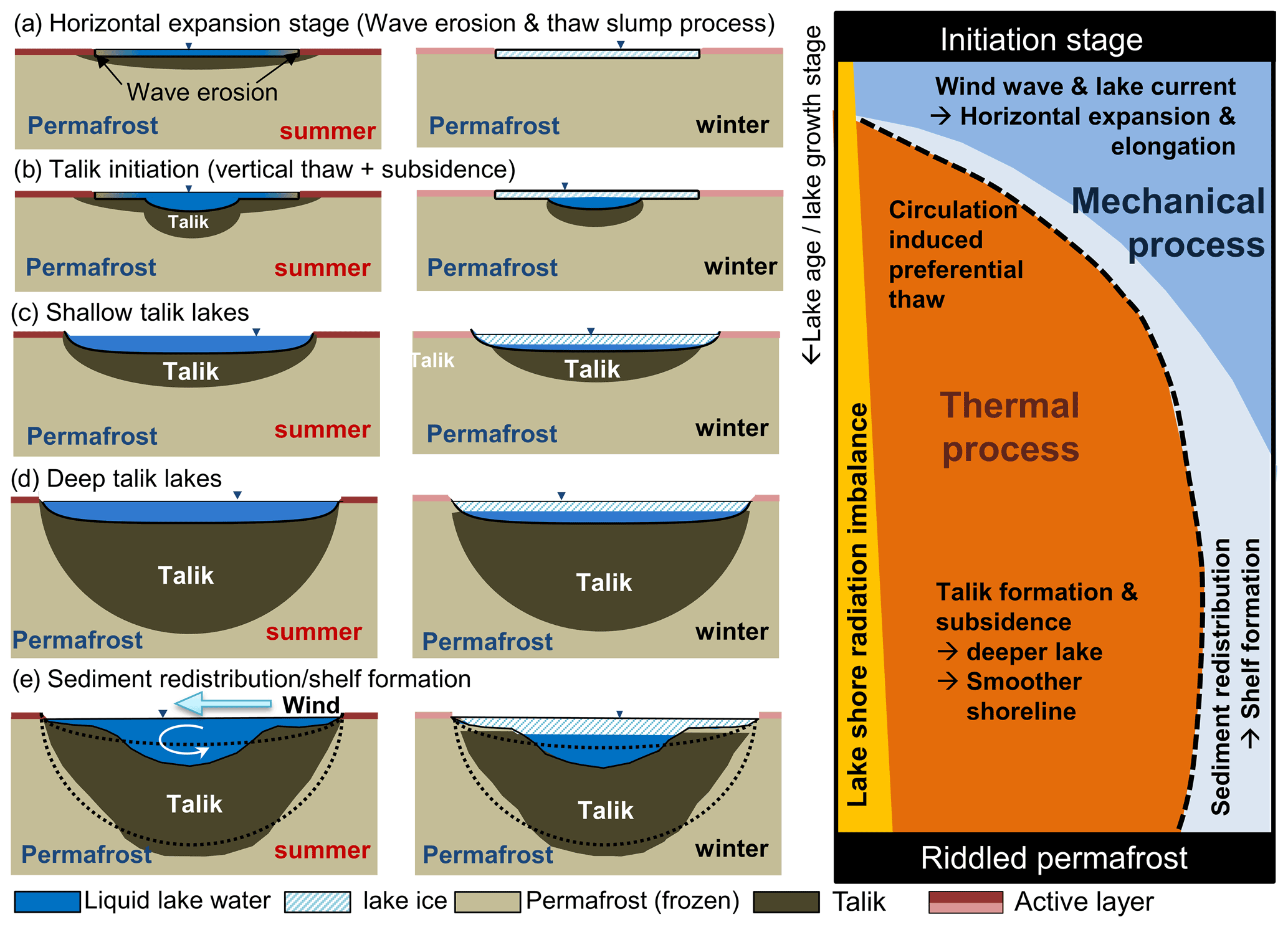
Figure 6Combined hypothetical models of thermokarst lake evolution and diagram of major influencing factors through time. The left column represents summer conditions, the center column represents winter conditions, and the right column indicates the corresponding importance of mechanical versus thermal processes through time as the lake ages (top is younger, bottom is older). Row (a) indicates the early processes under bedfast ice conditions before talik initiation. Row (b) shows the onset of vertical thaw and subsidence as talik begins to develop. Row (c) shows early, shallow talik growth conditions. Row (d) indicates later-stage processes on deepened talik due to vertical thaw. Row (e) is the mature stage of development when complex bathymetry has set in as a result of sediment transport.
Figure 6 illustrates the evolution of the talik in ice-rich permafrost over time, with driving processes shown in the right panel. In Stage A, the mechanical processes of wave erosion and thaw slumping along lake margins dominate lake expansion in summer, and shallow water favors grounded lake ice in the winter. In time (Stage B), the lake deepens from thaw subsidence beneath the older lake center. Winter ice may freeze to the lake bed, but heat loss is insufficient to freeze the underlying thawed lake bed sediments. A shallow talik develops as thermal processes work in tandem with mechanical processes, the latter now enhanced by more vigorous lake circulation. By Stage C, the talik is well developed beneath the entire lake basin as ground subsidence continues. Eventually (Stage D), the winter ice cover no longer extends to the lake bed but instead floats atop a residual pool of lake water, while the milder vertical temperature gradient beneath the lake deepens the talik as the lake matures. Thermomechanical erosion of lake margins, especially if there are prominent banks in hilly terrain, promotes sedimentation on near-shore shelves, and the underlying talik may begin refreezing. If the lake has not drained by this point (Stage E), the talik beneath the lake center extends deeper into the permafrost, although subsidence may cease as the excess ice content diminishes with depth. Where many large, old lakes exist, the permafrost may be riddled with deep taliks, and some may eventually penetrate to the permafrost base to create an open talik.
Talik development is affected by climatic and local conditions that favor talik initiation and growth including
-
deepening lake waters triggered by greater precipitation and/or reduced evaporation which promotes a floating ice regime
-
the presence of ice-rich sediments (e.g., Yedoma) beneath lakes
-
warmer lake water induced by regional warming or by longer ice-free summers
-
thinner winter ice cover due to warmer winter temperatures and/or deeper snow.
Conversely, talik growth cessation or contraction can occur when the same drivers are reversed if the lake partially or completely drains or when the lake basin is filled with sediments. The latter scenario is more likely in hilly terrain when the expanding lake erodes high banks and lake currents redistribute sediments.
4.2 Thermal process and preferential expansion
4.2.1 Lake geometry and heat balance
The analytical expression of the lake geometry may be useful to analyze horizontally oriented lakes with direction-dependent elongation as well. From Eqs. (28) and (1), we have
where a and b are the semi-major and semi-minor axes of the elongated lake, respectively. When horizontal heat conduction into the tundra is negligible , this equation can be reduced to
Hence, the aspect ratio of elliptic lakes can be explained by heat supply inequality if the lake geomorphology process is dominated by the thermal process. As expressed in Eq. (3), there are two different components in the incoming heat flux to the lake banks: surface energy flux and heat conduction from the lake water body. Thus, the lake aspect ratio may be written as
4.2.2 Incoming radiation imbalance effect
One of the incoming surface energy flux inequalities qsuf may be caused by shortwave radiation along the lake shoreline. The daily potential solar irradiation on a sloping surface can be computed by the trigonometric function (e.g., Eq. B.11 in DeWalle and Rango, 2008). The total daily radiation is a function of latitude and bank slope angle, which depend on the permafrost degradation rate, the maturity of the talik, and ground ice distribution. Figure 7 shows the computed mean daily potential solar irradiation on the sloping lakeshore () relative to a flat surface (Iq) during the summer period (June–August) at three different latitudes. The shape of this diagram may correspond to the shape of a thermokarst lake as the enhanced radiation results in more permafrost thaw. The difference in relative incoming radiation will diminish as bank slope angle lessens. In general, the south-facing slope along the northern shore tends to receive more radiation than the north-facing slope (e.g., Séjourné et al., 2015). This tendency is more pronounced in lower-latitude zones due to the higher mid-day sun angle.
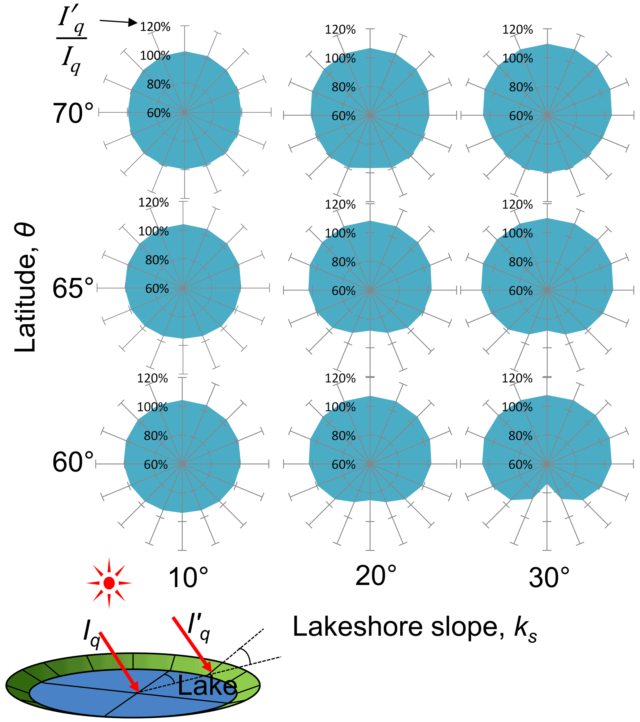
Figure 7Computed mean daily potential solar radiation on sloping lakeshore relative to the flat surface during the summer period (June–August) with respect to latitude. Iq is the potential solar radiation on a flat surface, and is radiation on the sloping lakeshore.
It is interesting that at 65 and 60∘ latitude the north- and south-facing banks receive slightly less radiation than east- and west-facing slopes, while an opposite result occurs at 70∘ latitude (Fig. 7). Therefore, the radiation imbalance may partially explain the north–south elongation along the 70∘ latitude line and the west–east elongation of lower latitude (60–65∘) of lowland thermokarst lakes shown by Grosse et al. (2013, their Fig. 19). However, because these small differences in incoming radiation imbalance alone are insufficient to result in the distinctive lake elongation in the ACP, they likely introduce rather minor additional complexities in lake spatial shape.
4.3 Wind wave erosion and preferential expansion
Wind wave erosion plays an important role in horizontal expansion of shallow lakes because waves can undercut the vegetated bank (Hopkins, 1949). Wind waves make the water bodies (e.g., lakes and bays) round by local net sediment flux even in low-latitude regions (e.g., Ashton et al., 2009). The effect of waves on shoreline morphology has been analyzed in the coastal engineering field: for example, Silvester (1974) investigated the equilibrium shape of bays under different wave conditions using laboratory wave experiments and found that the stable beach in the bay adapted a half-heart or cardioid shape for a fixed wave direction in the absence of sediment supply. Reeve et al. (2018) showed theoretically that the equilibrium coastline shape can be expressed as a diffusion-type equation through incorporating the wave diffraction effect, which makes the wave crest line nearly parallel to the shore. However, according to the shallow water wave theory, which is applicable for small fetch distances on lakes in the ACP, water waves do not cause any sediment transport without current, although wave motion is a key factor for the mobilization of the sediment (e.g., Carson and Hussey, 1962).
Wind-induced water circulation in a shallow, oval lake was perhaps first analyzed by Livingstone (1954) who showed theoretically that the current around the lake ends may be accelerated efficiently by wind-induced return rip currents. However, the lake water circulation pattern assumed in his study (shown in Fig. 8a) was less common than the pattern described by Carson and Hussey (1962), who observed reverse circulation patterns near the lake ends, as shown in Fig. 8b. For convenience, we refer to two distinctive current patterns: the Livingstone type and the Carson and Hussey (CandH) type. CandH-type circulation can indeed explain the commonly observed peat and sediment bars near the leeward lake side shores. Carson and Hussey (1962) noted that sedimentation on the leeward lake side can provide protection from mechanical wave erosion, as well as insulation from permafrost thaw, which results in lake elongation. They also observed that preferential bank erosion is typically focused in zones oriented 50∘ to wave approach. The return flow was found to concentrate around the windward lake side, which accelerates the mechanical erosion and sediment transport at the lake ends. However, the Livingstone-type circulation might occur depending on the local wind field as it can explain the sublittoral shelf formation on the windward shore. In either case, the wind-induced current effect on lake elongation can be supported by Livingstone's theory (1954) which should be valid for both circulation types. Thus, the combination of wind wave mobilization and lake water circulation is the most accepted hypothesis for lake elongation during the relatively young shallow lake expansion stage (Carson, 1968; Arp et al., 2011; Hinkel et al., 2012).
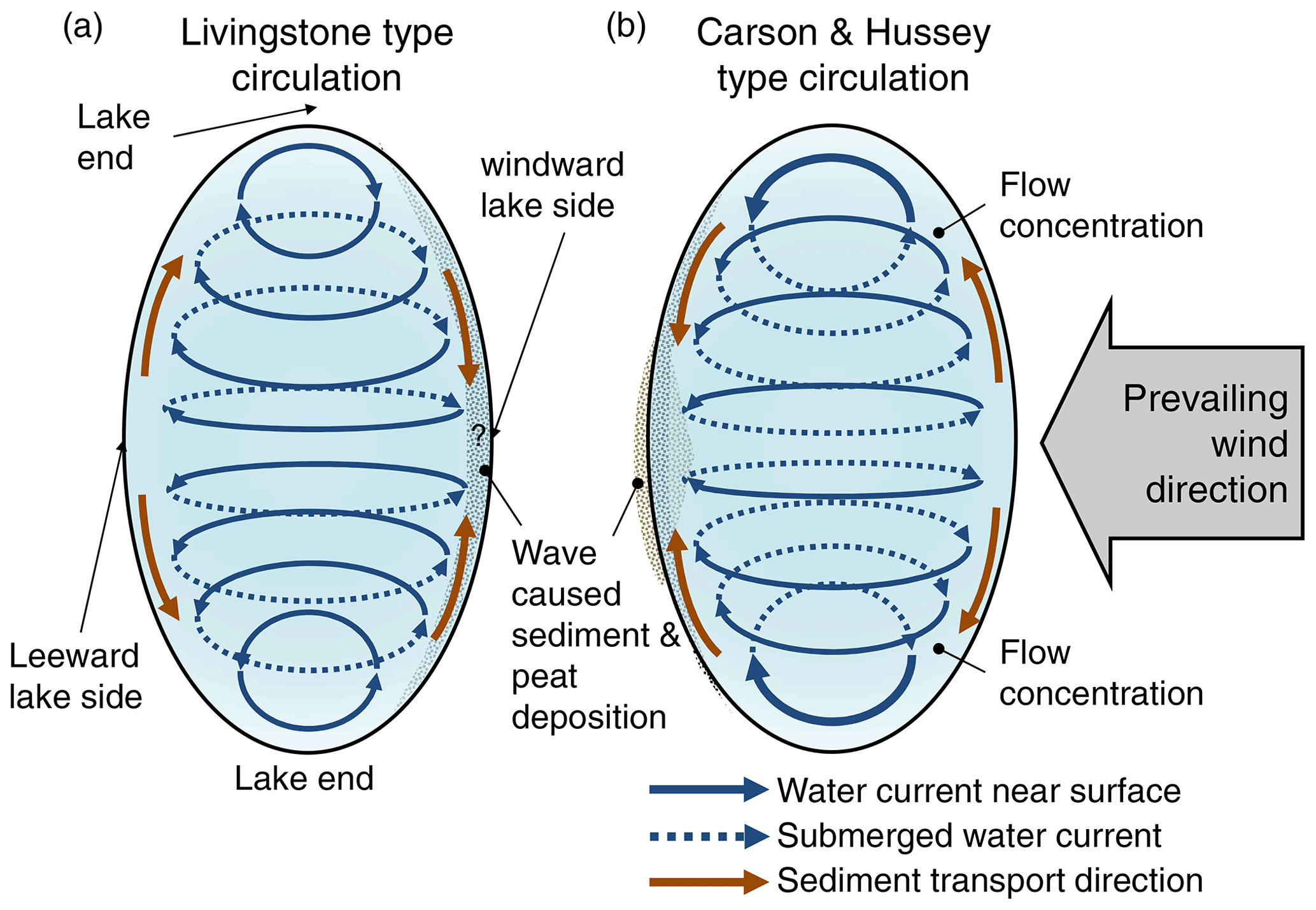
Figure 8Two distinctive lake water circulation patterns created by unidirectional wind. Livingstone-type circulation (a) and Carson and Hussey (CandH)-type circulation (b) cause opposite flow directions around lake ends. This also results in differences in sediment and peat deposition patterns.
The shallow wave theory states that the sediment mobilization due to wind wave only occurs in shallow water (wave height > 4 % of water depth; e.g., Reeve et al., 2018). Therefore, the contribution of the wind wave effect to lake elongation may be reduced as the lake deepens. Figure 9 shows a plot of lake length : width ratios versus the percent of lakes with a bedfast ice regime in seven study regions in Alaska determined with satellite-based synthetic aperture radar imagery (Engram et al., 2018). The study regions represent differences in permafrost characteristics and climate that appear to be reflected in this comparison of length : width ratio and the percent of lakes in a region that freeze to their bed and thus likely do not have a sub-lake talik. For example, lakes in the Teshekpuk Lake and Kuparuk study areas have a shape that is nearly twice as long as it is wide. In both of these regions, more than 80 % of the lakes freeze to their bed and likely do not have a talik. This is in contrast to lakes located near Umiat and on the Seward Peninsula that have primarily developed in Yedoma permafrost deposits. Lakes near Umiat and on the Seward Peninsula tend to be more circular (L : W = 1.3 to 1.4), and more than 90 % likely have a talik since they do not freeze to their bed in the winter. The differences observed here relative to elongation of lakes and whether the region primarily has lakes that freeze to their bed or not likely demonstrates a key aspect related to the role of wind wave erosion. In general, the shallower lakes common in coastal areas, such as Teshekpuk, Barrow, and Kuparuk, are more elongated likely due to wind wave erosion, whereas lakes in Umiat (ice-rich permafrost), Seward Peninsula (ice-rich permafrost), and Inigok (ice-poor permafrost) tend to be rounder because of talik development and the presence of deeper lakes (on the order of 10–20 m in some instances). This remote-sensing-based evidence implies that the wind effect seems to be limited by the lake thermal subsidence due to sub-lake talik development, while shallow lakes with the bedfast ice may continue elongating by wind erosion.
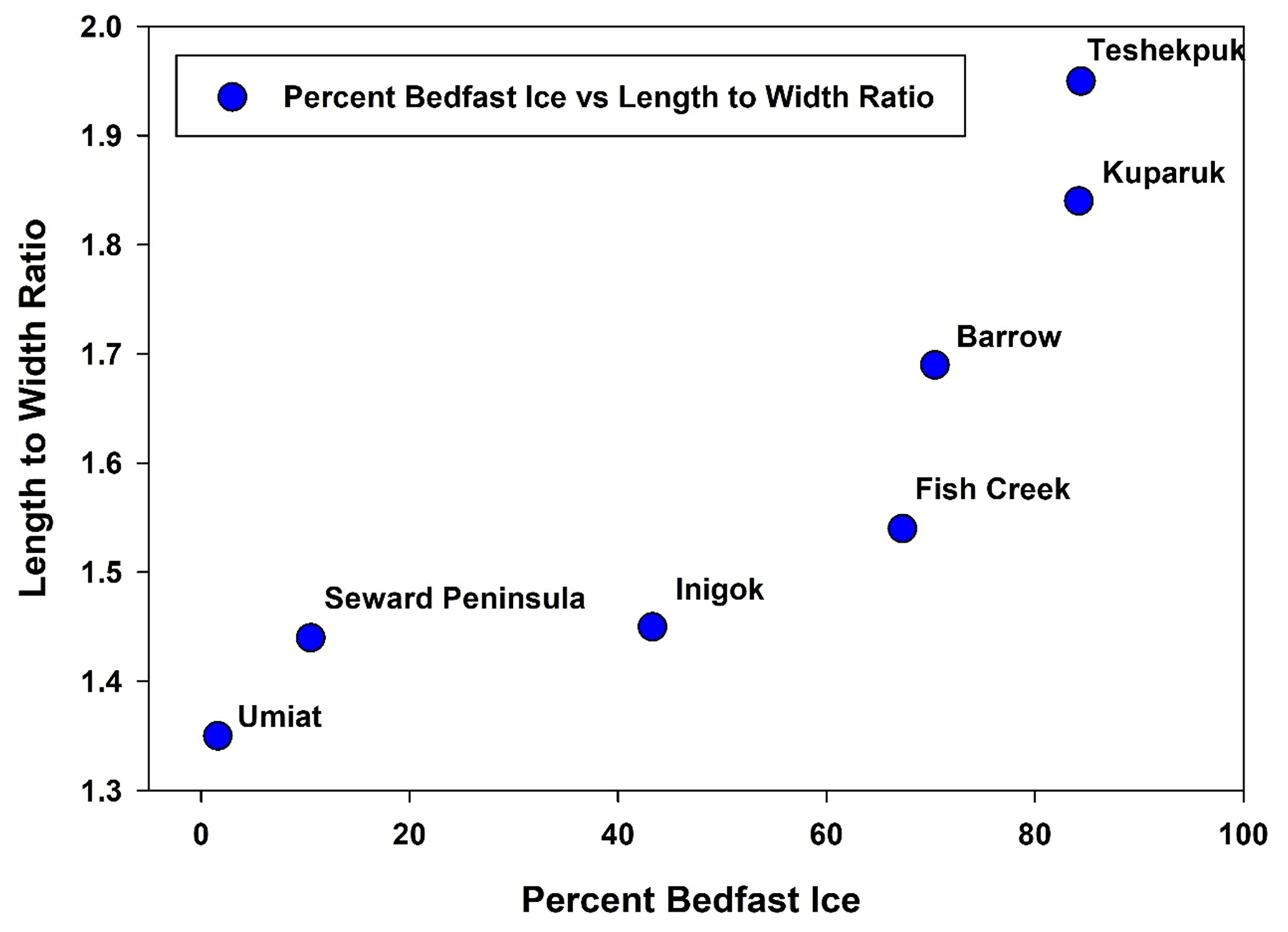
Figure 9Comparison of length to width ratio versus the percent of a particular region exhibiting a bedfast lake ice regime for seven study areas in Arctic Alaska. This analysis is based on synthetic aperture radar (SAR) satellite remote-sensing data presented in Engram et al. (2018). Lakes that are more elliptical in shape tend to occur where the majority of the lakes in the area freeze to their bed and thus likely do not have a talik. Lakes that are more circular in shape tend to occur where the majority of lakes in an area do not freeze to their bed and thus likely have a sub-lake talik.
4.4 Applicability of the 3D Stefan equation
The limitations of the derived 3D Stefan equation (Eq. 23) are summarized in this section along with Fig. 6. Once a seasonal pond is formed on the permafrost, it primarily expands horizontally by wind wave erosion and the thaw slump process (Livingstone, 1954; Carson and Hussey, 1962; Rex, 1961; Hinkel et al., 2012; Grosse et al., 2013) because the active layer beneath the pond likely freezes every year. On the flat ACP of Alaska, lake thaw slumps tend to be the result of topography (e.g., slope and aspect of the ground surface), while lake elongation is likely caused by wind wave erosion. As described above, preferential bank thaw at the lake ends can be explained by the insulation effect of the sediments carried by the water current (likely the CandH-type circulation) because the sublittoral shelf may be initiated at this stage.
When seasonal thawing penetrates more deeply than the annual freezing depth, a talik may be initiated, typically around the deepest point near the center of the lake (Lachenbruch et al., 1962). Sellmann (1975) described this process, which is one of the mechanisms for shelf formation in a thermokarst lake. For the horizontal expansion stage, A in Fig. 6, the proposed quasi-steady-state thermal model may not be appropriate because the lakeshore expansion imbalance occurs at least minimally throughout the lake expansion process. However, the 3D Stefan equation may be able to characterize the talik in the initiation stage B in Fig. 6.
Once the talik is established, the 3D Stefan thermal model proposed here suggests that the talik may begin to influence lake geometry. Since sediment mobilization due to wind-driven waves occurs in shallow water, lake elongation by waves may diminish as the lake deepens via ground subsidence (Fig. 9). Lake water effectively collects energy from the surface during summer, and the talik stores the excess heat throughout the winter. Arp et al. (2010, 2011) and Jeffries et al. (1999) discussed the difference in heat conduction between a grounded ice lake and a floating ice lake. Their observations are generally consistent with the proposed theory because a deeper talik under a floating ice lake should have a greater heat capacity. Since lake elongation likely occurs before talik formation, the horizontal lake characterization derived in this study may not be fully applicable to the analysis of thaw lakes on the ACP. In fact, the disagreement of the talik and lake extents in the Peatball Lake application illustrates the multiple effects on the lake bathymetry and orientation. Clearly, however, talik expansion and concurrent subsidence stabilize lake geometry and contribute to lake roundness.
The applicability of the proposed 3D Stefan equation is limited for lakes with high sediment influx and for lakes with talik. The paired sublittoral shelves on both lake sides are commonly found in the sand dune areas of the southern ACP. The talik shape is likely altered by uneven sediment deposition that affects the temperature gradient normal to the phase boundary as mentioned by several researchers (Hunter et al., 1981; Mackay, 1992; West and Plug, 2008). The shelves created by sediment redistribution due to lake water circulation adds complexity to the ellipsoidal talik shape described in this study. Finally, if the talik penetrates through the permafrost and becomes a throughgoing talik (Hinkel and Arp, 2015), the proposed thermal theory herein is no longer applicable for thermokarst lake and talik characterization.
Lastly, the 3D Stefan equation assumes fully saturated talik and isotropic thermal properties. However, uneven consolidation of thawed porous media and layered structure of the permafrost may cause anisotropic thermal conductivities. When the effect of direction dependency in the thermal conductivity is found to be significant, it can be incorporated into the formulation of the anisotropic heat conduction into the permafrost.
The theory presented here addresses the origin of the thermokarst lake ellipticity on the ACP. Elliptic lake geometry results from minimizing overall thawing energy consumption for a given incoming energy load. This is particularly applicable for mature, deep thermokarst lakes with well-developed taliks. Additionally, existing hypothetical models were reviewed to illuminate the thermal effect (e.g., ellipsoidal talik geometry) on the thermokarst lake morphology.
The derived ellipsoid talik model integrates the atmospheric forcing (or incoming energy), the vertical thermal gradient, the thermal diffusivity of the permafrost, and the talik geometry. Heat flux by conduction into the permafrost depends on the heat gradient of the underlying permafrost (Fourier's law). As the vertical temperature slope diminishes with talik maturation, the depth : width ratio of the talik becomes larger, creating a deeper talik; thus, much of incoming energy is likely consumed for vertical rather than horizontal expansion. Conversely, during the early stages, thermomechanical processes such as wind-driven wave erosion dominate horizontal expansion and elongation of the lake. Consequently, this theory elucidates how talik expansion and concurrent permafrost degradation stabilize the shape of a thermokarst lake to one that is more round rather than elliptical.
The semi-ellipsoidal 3D Stefan equation is, to our knowledge, the first geometric model explicitly derived only from the energy conservation equation at the phase boundary. The vector form of the energy conservation equation (Eq. 5) in a 3D anisotropic thermal field was integrated at the phase boundary area under the isolated general-shaped lake to quantify the total energy balance. It was shown that the basin total thaw energy or talik expansion rate is equivalent to the weighted phase boundary area. The optimum talik shape function was determined by the variational principle as an extremum of the functional that minimizes the total thawing energy consumption (the stationary action principle). Thus, the resultant semi-ellipsoid equation (Eq. 23) can be considered the 3D Stefan equation because it describes the optimum geometry of phase boundary.
The derived semi-ellipsoid function was applied to Peatball Lake, ACP of Alaska, where the talik was extensively surveyed using TEM soundings. The pure geometric fitting exercise met the 27 measured TEM data point well with RMSD of 5.94 m, although the talik orientation disagreed with orientation of Peatball Lake and other surrounding lakes. This may be induced by the irregularity due to the rapid and uneven horizontal lake expansion or possibly by basin coalescence. Comparing the observed talik thickness to the observed lake bathymetry indicated two distinctive permafrost degradation scenarios: significant subsidence by near-surface ice-rich-layer thaw and the minor contribution of subsidence due to ice-poor permafrost thaw at depth. Consequently, lake water depth is affected by uneven subsidence of thawing permafrost and the interannual water balance; the spatial lake shape irregularity was determined during an earlier stage of development. Therefore, careful consideration is required for the analysis of the relationship between lake bathymetry and talik thickness. Nevertheless, this theoretical technique can be used as guidance to partition various effects such as talik development and thaw subsidence, wind wave erosion, lake ice thickness, surficial geology type, and sediment transport by lake water current. Moreover, the analytical expression of the 3D Stefan equation can be potentially incorporated in the global- or regional-scale Earth system model to describe missing sub-grid-scale processes such as lake dynamics with minimal additional computational resources.
Alternative derivation may provide the thermally optimum talik shape minimizing the phase boundary area A with a fixed talik volume V. Equation (15) establishes talik volume and phase boundary area under the thermokarst lake by a general function of the phase boundary φ. The horizontal coordinate system may be transformed by . Then, the phase boundary can be expressed as a scaled function:
According to
the talik volume and the phase boundary area can be written as
where denotes the extent of on the uv plane, and is the surface on as
The horizontal scaling transform makes it a symmetric closed surface on z=0:
It is known that volume U enclosed by the ovaloid surface S∗ and its surface area satisfy the isoperimetric inequality for an ovaloid surface, which can be written as
As the volume and the surface area of the convex closed surface S∗ can be expressed as
we have
The equality in Eq. (A10) holds only if the surface S* is a sphere, which maximizes the volume. Let the radius of this sphere be
From the symmetricity to the plane z=0, we can obtain
Inverse scaling coordinate transformation yields the ellipsoid phase boundary function as follows:
where D is the depth of the talik at the center. The ellipsoid, the 3D Stefan equation for talik, can be obtained by the isoperimetric inequality, as well as the functional analysis.
We can determine two coefficients in the ellipsoid (Eq. 21) by further application of the variational principle. Let
Also, let the intersect d be proportional to the vertical radius of the ellipsoid as follows:
where t is a parameter describing the relative elevation of the basin to the original ground surface. Then, Eqs. (20) and (21) can be rewritten as
Now, the phase boundary area and volume can be evaluated as functions of the parameter t:
Eliminating D from these expressions yields
where M is a positive constant. Therefore, as
the phase boundary area A[φ] is the minimum at t=0. Hence, d=0, which corresponds to a semi-ellipsoid with depth D at the center.
Data used in this research are either available from other sources as referenced within the paper or in Parsekian et al. (2018, https://doi.org/10.18739/A20K35) and Engram (2018, https://doi.org/10.18739/A2CJ87K8H).
NO and KY developed the theory, and all other co-authors, especially KMH, BMJ, ADP, and MK, offered crucial advice in interpretation. BMJ and ADP provided the field-observed data for the case study of Peatball Lake. BMJ performed the statistical analysis on the oriented lakes based on SAR satellite remote-sensing data. RCR, ALB, and HB actively participated in the discussions and manuscript improvement. NO prepared the manuscript with contributions from all co-authors.
The contact author has declared that neither they nor their co-authors have any competing interests.
Publisher's note: Copernicus Publications remains neutral with regard to jurisdictional claims in published maps and institutional affiliations.
This study was supported by the National Science Foundation (NSF) under awards OPP-1806287, 1806213, and 1806202. The authors thank UIC Science and CH2MHill Polar Field Services (now Battelle Arctic Research Operations) for logistical field support. Datasets and sources code for this research are available in these in-text data citation references. Louise Farquharson and Benjamin Gaglioti provided helpful comments improving the manuscript.
This research has been supported by the National Science Foundation, Directorate for Geosciences (grant no. OPP-1806202, OPP-1806287, and OPP-1806213).
This paper was edited by Christian Hauck and reviewed by two anonymous referees.
Arp, C. D., Jones, B. M., Schmutz, J. A., Urban, F. E., and Jorgenson, M. T.: Two mechanisms of aquatic and terrestrial habitat change along an Alaskan Arctic coastline, Polar Biol., 33, 1629–1640, 2010.
Arp, C. D., Jones, B. M., Urban, F. E., and Grosse, G.: Hydrogeomorphic processes of thermokarst lakes with grounded-ice and floating-ice regimes on the Arctic coastal plain, Alaska, Hydrol. Process., 25, 2422–2438, 2011.
Arp, C. D., Whitman, M. S., Jones, B. M., Kemnitz, R., Grosse, G., and Urban, F. E.: Drainage network structure and hydrologic behavior of three lake-rich watersheds on the Arctic Coastal Plain, Alaska, Arct. Antarct. Alp. Res., 44, 385–398, 2012.
Arp, C. D., Jones, B. M., Liljedahl, A. K., Hinkel, K. M., and Welker, J. A.: Depth, ice thickness, and ice-out timing cause divergent hydrologic responses among Arctic lakes, Water Resour. Res., 51, 9379–9401, 2015.
Arp, C. D., Jones, B. M., Grosse, G., Bondurant, A. C., Romanovsky, V. E., Hinkel, K. M., and Parsekian, A. D.: Threshold sensitivity of shallow Arctic lakes and sublake permafrost to changing winter climate, Geophys. Res. Lett., 43, 6358–6365, 2016.
Ashton, A. D., Murray, A. B., Littlewood, R., Lewis, D. A., and Hong, P.: Fetch-limited self-organization of elongate water bodies, Geology, 37, 187–190, 2009.
Black, R. F. and Barksdale, W. L.: Oriented lakes of northern Alaska, J. Geol., 57, 105–118, 1949.
Brewer, M. C.: The thermal regime of an arctic lake, Eos T. Am. Geophys. Un., 39, 278–284, 1958.
Burn, C. R.: Tundra lakes and permafrost, Richards Island, western Arctic coast, Canada, Can. J. Earth Sci., 39, 1281–1298, 2002.
Burn, C. R. and Smith, M. W.: Development of thermokarst lakes during the Holocene at sites near Mayo, Yukon Territory, Permafrost Periglac., 1, 161–175, 1990.
Carslaw, H. S. and Jaeger, J. C.: Conduction of heat in solids, Oxford, Clarendon Press, ISBN-10: 0198533683, 1959.
Carson, C. E.: Radiocarbon dating of lacustrine strands in Arctic Alaska, Arctic, 21, 12–26, https://doi.org/10.14430/arctic3242, 1968.
Carson, C. E. and Hussey, K. M.: The oriented lakes of Arctic Alaska, J. Geol., 70, 417–439, 1962.
Carter, L. D.: A Pleistocene sand sea on the Alaskan Arctic coastal plain, Science, 211, 381–383, 1981.
Cassel, K. W.: Variational methods with applications in science and engineering, Cambridge University Press, https://doi.org/10.1017/CBO9781139136860, 2013.
Courant, R. and Hilbert, D.: Methods of mathematical physics, B. Am. Math. Soc., 60, 578–579, 1954.
Creighton, A. L., Parsekian, A. D., Angelopoulos, M., Jones, B. M., Bondurant, A., Engram, M., and Arp, C. D.: Transient electromagnetic surveys for the determination of talik depth and geometry beneath thermokarst lakes, J. Geophys. Res.-Sol. Ea., 123, 9310–9323, 2018.
Czudek, T. and Demek, J.: Thermokarst in Siberia and its influence on the development of lowland relief, Quaternary Res., 1, 103–120, 1970.
Devoie, É.G., Craig, J. R., Dominico, M., Carpino, O., Connon, R. F., Rudy, A. C., and Quinton, W. L.: Mechanisms of Discontinuous Permafrost Thaw in Peatlands, J. Geophys. Res.-Earth, 126, e2021JF006204, https://doi.org/10.1029/2021JF006204, 2021.
DeWalle, D. R. and Rango, A.: Principles of snow hydrology, Cambridge University Press, https://doi.org/10.1017/CBO9780511535673, 2008.
Doolittle, J. A., Hardisky, M. A., and Gross, M. F.: A ground-penetrating radar study of active layer thicknesses in areas of moist sedge and wet sedge tundra near Bethel, Alaska, USA, Arctic Alpine Res., 22, 175–182, 1990.
Engram, M.: Floating and bedfast lake ice regimes across Arctic Alaska using space-borne SAR imagery from 1992–2016, Arctic Data Center [data set], https://doi.org/10.18739/A2CJ87K8H, 2018.
Engram, M., Arp, C. D., Jones, B. M., Ajadi, O. A., and Meyer, F. J.: Analyzing floating and bedfast lake ice regimes across Arctic Alaska using 25 years of space-borne SAR imagery, Remote Sens. Environ., 209, 660–676, 2018.
Farquharson, L., Anthony, K. W., Bigelow, N., Edwards, M., and Grosse, G.: Facies analysis of yedoma thermokarst lakes on the northern Seward Peninsula, Alaska, Sediment. Geol., 340, 25–37, 2016.
French, H. M.: The Periglacial Environment, 4th Edn., John Wiley and Sons Ltd., Chichester, UK, 515 pp., ISBN: 978-1-119-13278-3, 2018.
Gelfand, I. M. and Fomin, S. V.: Calculus of variations, revised English edition translated and edited by: Silverman, R. A., Prentice Hall, Englewood Clims, NJ, 7, 10–11, 1963.
Grosse, G., Jones, B. M., and Arp, C. D.: Thermokarst lakes, drainage, and drained basins, in: Treatise on Geomorphology, edited by: Shroder, J., Giardino, R., and Harbor, J., Academic Press, San Diego, CA, vol. 8, Glacial and Periglacial Geomorphology, 325–353, https://doi.org/10.1016/B978-0-12-374739-6.00216-5, 2013.
Heslop, J. K., Walter Anthony, K. M., Sepulveda-Jauregui, A., Martinez-Cruz, K., Bondurant, A., Grosse, G., and Jones, M. C.: Thermokarst lake methanogenesis along a complete talik profile, Biogeosciences, 12, 4317–4331, https://doi.org/10.5194/bg-12-4317-2015, 2015.
Hinkel, K. M. and Arp, C.: Estimating talik depth beneath lakes in Arctic Alaska, in: Proceedings 7th Canadian Permafrost Conference and 68th Canadian Geotechnical Conference, Quebec City, Canada, 20–23, 2015.
Hinkel, K. M., Frohn, R. C., Nelson, F. E., Eisner, W. R., and Beck, R. A.: Morphometric and spatial analysis of thaw lakes and drained thaw lake basins in the western Arctic Coastal Plain, Alaska, Permafrost Periglac., 16, 327–341, 2005.
Hinkel, K. M., Sheng, Y., Lenters, J. D., Lyons, E. A., Beck, R. A., Eisner, W. R., and Wang, J.: Thermokarst lakes on the Arctic coastal plain of Alaska: geomorphic controls on bathymetry, Permafrost Periglac., 23, 218–230, 2012.
Hopkins, D. M.: Thaw lakes and thaw sinks in the Imuruk Lake area, Seward Peninsula, Alaska, J. Geol., 57, 119–131, 1949.
Hopkins, D. M., Karlstrom, T., Black, R., Williams, J., Pewe, T., Fernold, A., and Muller, E.: Permafrost and ground water in Alaska, a shorter contribution to the general geology, US Geol. Surv. Prof. Paper 264, 1955.
Hunter, J. A., MacAulay, H. A., Gagné, R. M., Burns, R. A., Harrison, T. E., and Hawkins, J. P.: Drained lake experiment for investigation of growth of permafrost at Illisarvik, Northwest Territories – initial geophysical results, Current research, part C. Geological Survey of Canada, Paper, 67–76, 1981.
Jeffries, M. O., Morris, K., and Liston, G. E.: A method to determine lake depth and water availability on the North Slope of Alaska with spaceborne imaging radar and numerical ice growth modelling, Arctic, 49, 367–374, https://doi.org/10.14430/arctic1212, 1996.
Jeffries, M. O., Zhang, T., Frey, K., Kozlenko, N.: Estimating late-winter heat flow to the atmosphere from the lake-dominated Alaskan North Slope, J. Glaciol., 45, 315–24, https://doi.org/10.3189/S0022143000001817, 1999.
Johnston, G. H. and Brown, R. J. E.: Occurrence of permafrost at an Arctic lake, Nature, 211, 952–953, 1966.
Jones, B. M., Grosse, G. D. A. C., Arp, C. D., Jones, M. C., Anthony, K. W., and Romanovsky, V. E.: Modern thermokarst lake dynamics in the continuous permafrost zone, northern Seward Peninsula, Alaska, J. Geophys. Res.-Biogeo., 116, G00M03, https://doi.org/10.1029/2011JG001666, 2011.
Jones, B. M., Grosse, G., Farquharson, L. M., Roy-Léveillée, P., Veremeeva A., Kanevskiy, M. Z., Gaglioti, B. V., Breen, A. L., Parsekian, A. D., Ulrich, M., and Hinkel, K. M.: Lake and drained lake basin systems in lowland permafrost regions, Nature Rev. Earth Environ., 3, 85–98, https://doi.org/10.1038/s43017-021-00238-9, 2022.
Jorgenson, M. T.: Thermokarst terrains, in: Treatise on Geomorphology, edited by: Shroder, J., Giardino, R., amd Harbor, J., Academic Press, San Diego, CA, vol. 8, Glacial and Periglacial Geomorphology, 313–324, 2013.
Jorgenson, M. T. and Shur, Y.: Evolution of lakes and basins in northern Alaska and discussion of the thaw lake cycle, J. Geophys. Res.-Earth, 112, F02S17, https://doi.org/10.1029/2006JF000531, 2007.
Jorgenson, T., Yoshikawa, K., Kanevskiy, M., Shur, Y., Romanovsky, V., Marchenko, S., Grosse, G., Brown, J., and Jones, B.: Permafrost characteristics of Alaska, in: Proceedings of the 9th International Conference on Permafrost, edited by: Kane, D. L. and Hinkel, K. M., Extended Abstracts, 29 June–3 July 2008, Fairbanks, AK, Institute of Northern Engineering, University of Alaska Fairbanks, 121–122, 2008.
Kanevskiy, M., Shur, Y., Fortier, D., Jorgenson, M. T., and Stephani, E.: Cryostratigraphy of late Pleistocene syngenetic permafrost (yedoma) in northern Alaska, Itkillik River exposure, Quaternary Res., 75, 584–596, 2011.
Kanevskiy, M., Shur, Y., Jorgenson, M. T., Ping, C. L., Michaelson, G. J., Fortier, D., and Tumskoy, V.: Ground ice in the upper permafrost of the Beaufort Sea coast of Alaska, Cold Reg. Sci. Technol., 85, 56–70, 2013.
Kessler, M. A., Plug, L. J., and Anthony, K. W.: Simulating the decadal-to millennial-scale dynamics of morphology and sequestered carbon mobilization of two thermokarst lakes in NW Alaska, J. Geophys. Res.-Biogeo., 117, G00M06, https://doi.org/10.1029/2011JG001796, 2012.
Kurylyk, B. L. and Hayashi, M.: Improved Stefan equation correction factors to accommodate sensible heat storage during soil freezing or thawing, Permafrost Periglac., 27, 189–203, 2016.
Lachenbruch, A. H., Brewer, M. C., Greene, G. W., and Marshall, B. V.: Temperatures in permafrost, in: Temperature – Its Measurement and Control in Science and Industry, edited by: Herzfeld, C. M., 3, Reinhold Publishing, New York, 791–803, 1962.
Lenz, J., Jones, B. M., Wetterich, S., Tjallingii, R., Fritz, M., Arp, C. D., Rudaya, N., and Grosse, G.: Impacts of shore expansion and catchment characteristics on lacustrine thermokarst records in permafrost lowlands, Alaska Arctic Coastal Plain, arktos, 2, 1–5, 2016.
Ling, F. and Zhang, T.: Impact of the timing and duration of seasonal snow cover on the active layer and permafrost in the Alaskan Arctic, Permafrost Periglac., 14, 141–150, 2003a.
Ling, F. and Zhang, T.: Numerical simulation of permafrost thermal regime and talik development under shallow thaw lakes on the Alaskan Arctic Coastal Plain, J. Geophys. Res., 108, 4511, https://doi.org/10.1029/2002JD003014, 2003b.
Livingstone, D. A.: On the orientation of lake basins, Am. J. Sci., 252, 547–554, 1954.
Lunardini, V. J.: Heat Transfer in Cold Climates, Van Nostrand Reinhold Co., New York, NY, 731, ISBN: 9780442262501, 1981.
Mackay, J. R.: Pingos of the Pleistocene Mackenzie delta area, Geograph. Bull., 18, 1–63, 1962.
Mackay, J. R.: Lake stability in an ice-rich permafrost environment: examples from the western Arctic coast, in: Aquatic Ecosystems in Semi-Arid Regions: Implications for Resource Management, edited by: Robarts, R. D. and Bothwell, M. L., NHRI Symposium Series 7, Environment Canada, Saskatoon, Saskatchewan, 1–26, 1992.
McClymont, A. F., Hayashi, M., Bentley, L. R., and Christensen, B. S.: Geophysical imaging and thermal modeling of subsurface morphology and thaw evolution of discontinuous permafrost, J. Geophys. Res.-Earth, 118, 1826–1837, 2013.
Ohara, N. and Yamatani, K.: Theoretical Stable Hydraulic Section based on the Principle of Least Action, Sci. Rep., 9, 7957, https://doi.org/10.1038/s41598-019-44347-4, 2019.
O'Neill, H. B., Roy-Leveillee, P., Lebedeva, L., and Ling, F.: Recent advances (2010–2019) in the study of taliks, Permafrost Periglac., 31, 346–357, 2020.
Painter, S. L., Coon, E. T., Atchley, A. L., Berndt, M., Garimella, R., Moulton, J. D., and Wilson, C. J.: Integrated surface/subsurface permafrost thermal hydrology: Model formulation and proof-of-concept simulations, Water Resour. Res., 52, 6062–6077, 2016.
Parsekian, A. D., Creighton, A. L., Jones, B. M., Bondurant, A., and Arp, C. D.: Arctic lake transient electromagnetic (TEM) soundings 2016–2017, Arctic Data Center [data set], https://doi.org/10.18739/A20K35, 2018.
Parsekian, A. D., Creighton, A. L., Jones, B. M., and Arp, C. D.: Surface nuclear magnetic resonance observations of permafrost thaw below floating, bedfast, and transitional ice lakes, Geophysics, 84, EN33–EN45, 2019.
Patel, P. D.: Interface conditions in heat-conduction problems with change of phase, AIAA J., 6, 2454–2454, 1968.
Pilon, J. A., Annan, A. P., and Davis, J. L.: Monitoring permafrost ground conditions with ground probing radar (GPR), in: Workshop on Permafrost Geophysics, Golden, Colarado, US Army Corps of Engineers, Cold Regions Research and Engineering Laboratory, Hanover, New Hampshire, CRREL Special Report, 85 pp., 1985.
Plug, L. J., and West, J. J.: Thaw lake expansion in a two-dimensional coupled model of heat transfer, thaw subsidence, and mass movement, J. Geophys. Res.-Earth, 114, F01002, https://doi.org/10.1029/2006JF000740, 2009.
Rampton, V. N.: Quaternary geology of the Yukon coastal plain, ISBN: 9780660106373, 1982.
Rangel, R. C., Parsekian, A. D., Farquharson, L. M., Jones, B. M., Ohara, N., Creighton, A. L., Gaglioti, B. V., Kanevskiy, M., Breen, A. L., Bergstedt, H., Romanovsky, V. E., and Hinkel, K. M.: Geophysical Observations of Taliks Below Drained Lake Basins on the Arctic Coastal Plain of Alaska, J. Geophys. Res.-Sol. Ea. 126, e2020JB020889 https://doi.org/10.1029/2020JB020889, 2021.
Reeve, D., Chadwick, A., and Fleming, C.: Coastal engineering: processes, theory and design practice, CRC Press, https://doi.org/10.2112/JCOASTRES-D-19A-00014.1, 2018.
Rex, R. W.: Hydrodynamic analysis of circulation and orientation of lakes in Northern Alaska, in: Geology of the Arctic, edited by: Rauch, G. O., University of Toronto Press, Toronto, eISBN: 978-1-4875-8496-2, 1021–1043, 1961.
Rowland, J. C., Travis, B. J., and Wilson, C. J.: The role of advective heat transport in talik development beneath lakes and ponds in discontinuous permafrost, Geophys. Res. Lett., 38, L17504, https://doi.org/10.1029/2011GL048497, 2011.
Roy-Leveillee, P. and Burn, C. R.: Near-shore talik development beneath shallow water in expanding thermokarst lakes, Old Crow Flats, Yukon, J. Geophys. Res.-Earth, 122, 1070–1089, 2017.
Schirrmeister, L., Froese, D., Tumskoy, V., Grosse, G., and Wetterich, S.: Yedoma: Late Pleistocene ice-rich syngenetic permafrost of Beringia, Encyclopedia of Quaternary Science, 2nd Edn., Elsevier, 542–552, https://doi.org/10.1016/B978-0-444-53643-3.00106-0, 2013.
Schuur, E. A., McGuire, A. D., Schädel, C., Grosse, G., Harden, J. W., Hayes, D. J., and Natali, S. M.: Climate change and the permafrost carbon feedback, Nature, 520, 171–179, 2015.
Schwamborn, G., Andreev, A., Rachold, V., Hubberten, H. W., Grigoriev, M. N., Tumskoy, V., and Dorozkhina, M. V.: Evolution of Lake Nikolay, Arga Island, Western Lena River delta, during late Pleistocene and Holocene time, Polarforschung, 70, 69–82, 2000.
Séjourné, A., Costard, F., Fedorov, A., Gargani, J., Skorve, J., Massé, M., and Mège, D.: Evolution of the banks of thermokarst lakes in Central Yakutia (Central Siberia) due to retrogressive thaw slump activity controlled by insolation, Geomorphology, 241, 31–40, 2015.
Sellmann, P. V.: The classification and geomorphic implications of thaw lakes on the Arctic Coastal Plain, Alaska, Vol. 344, US Department of Defense, Department of the Army, Corps of Engineers, Cold Regions Research and Engineering Laboratory, Report, 21 pp., 1975.
Shur, Y. and Osterkamp, T.: Thermokarst, Report INE 06.11. University of Alaska Fairbanks, Institute of Northern Engineering, Fairbanks, AK, 50 pp., 2007.
Silvester, R.: Coastal Engineering, Vols. 1 and 2, Elsevier, Oxford, ISBN-10: 0444411011, 1974.
Silvester, R. and Hsu, J. R.: Coastal Stabilization, Advanced Series on Ocean Engineering, 14, ISBN 10: 9810231377, ISBN 13: 9789810231378, 1997.
Singer-Loginova, I. and Singer, H. M.: The phase field technique for modeling multiphase materials, Reports on progress in physics, 71, 106501, https://doi.org/10.1088/0034-4885/71/10/106501, 2008.
Stefan, J.: Über die Theorie der Eisbildung, insbesondere über die Eisbildung im Polarmee, Ann. Phys. Chem., 42, 269–286, 1891.
Sullivan, T. D., Parsekian, A. D., Sharp, J., Hanke, P. J., Thalasso, F., Shapley, M., and Walter Anthony, K.: Influence of permafrost thaw on an extreme geologic methane seep, Permafrost Periglac., 32, 484–502, https://doi.org/10.1002/ppp.2114, 2021.
Tomirdiaro, S. V.: Evolution of lowland landscapes in northeastern Asia during late Quaternary time, in: Paleoecology of Beringia, Academic Press, 29–37, https://doi.org/10.1016/B978-0-12-355860-2.50009-0, 1982.
van Everdingen, R. O. (Ed.): Multi-Language Glossary of Permafrost and Related Ground-ice Terms, International Permafrost Association, The Arctic Institute of North America, University of Calgary, Calgary, 268 pp., 1998.
West, J. J. and Plug, L. J.: Time-dependent morphology of thaw lakes and taliks in deep and shallow ground ice, J. Geophys. Res., 113, F01009, https://doi.org/10.1029/2006JF000696, 2008.
Westermann, S., Schuler, T. V., Gisnås, K., and Etzelmüller, B.: Transient thermal modeling of permafrost conditions in Southern Norway, The Cryosphere, 7, 719–739, https://doi.org/10.5194/tc-7-719-2013, 2013.
- Abstract
- Introduction
- Theory
- Case study
- Discussion
- Conclusions
- Appendix A: Alternative derivation using isoperimetric inequality
- Appendix B: Determination of the coefficients d and λ
- Data availability
- Author contributions
- Competing interests
- Disclaimer
- Acknowledgements
- Financial support
- Review statement
- References