the Creative Commons Attribution 4.0 License.
the Creative Commons Attribution 4.0 License.
 | 30 Jun 2020
Past ice sheet–seabed interactions in the northeastern Weddell Sea embayment, Antarctica
Robert D. Larter
Claus-Dieter Hillenbrand
Simon H. Sørli
Matthias Forwick
James A. Smith
Lukas Wacker
The Antarctic ice sheet extent in the Weddell Sea embayment (WSE) during the Last Glacial Maximum (LGM; ca. 19–25 calibrated kiloyears before present, ka cal BP) and its subsequent retreat from the shelf are poorly constrained, with two conflicting scenarios being discussed. Today, the modern Brunt Ice Shelf, the last remaining ice shelf in the northeastern WSE, is only pinned at a single location and recent crevasse development may lead to its rapid disintegration in the near future. We investigated the seafloor morphology on the northeastern WSE shelf and discuss its implications, in combination with marine geological records, to create reconstructions of the past behaviour of this sector of the East Antarctic Ice Sheet (EAIS), including ice–seafloor interactions. Our data show that an ice stream flowed through Stancomb-Wills Trough and acted as the main conduit for EAIS drainage during the LGM in this sector. Post-LGM ice stream retreat occurred stepwise, with at least three documented grounding-line still-stands, and the trough had become free of grounded ice by ∼10.5 ka cal BP. In contrast, slow-flowing ice once covered the shelf in Brunt Basin and extended westwards toward McDonald Bank. During a later time period, only floating ice was present within Brunt Basin, but large “ice slabs” enclosed within the ice shelf occasionally ran aground at the eastern side of McDonald Bank, forming 10 unusual ramp-shaped seabed features. These ramps are the result of temporary ice shelf grounding events buttressing the ice further upstream. To the west of this area, Halley Trough very likely was free of grounded ice during the LGM, representing a potential refuge for benthic shelf fauna at this time.
- Article
(24723 KB) - Full-text XML
-
Supplement
(430 KB) - BibTeX
- EndNote


In Antarctica, the largest uncertainty for the grounding-line position of the ice sheet at the Last Glacial Maximum (LGM) exists in the Weddell Sea embayment (WSE; The RAISED Consortium et al., 2014). Two conflicting scenarios were proposed for the reconstructed position of the LGM grounding line: in one scenario, which is predominantly based on marine geological and geophysical information, the grounding line is located near the shelf edge (Hillenbrand et al., 2012, 2014; Larter et al., 2012). The alternative scenario is mainly based on cosmogenic nuclide exposure dates on terrestrial samples from the eastern and southwestern hinterland of the WSE, which, in combination with ice sheet modelling, indicate only limited thickening of the East Antarctic Ice Sheet (EAIS) during the LGM and reconstructs a grounding-line position about 650 km further south in Filchner Trough (Hillenbrand et al., 2014; Bentley et al., 2010; Hein et al., 2011). However, newly published terrestrial data from around the WSE indicate thickening of the EAIS during the LGM and that previous terrestrial studies were influenced by cosmogenic nuclide inheritance due to surface preservation caused by coverage with cold-based ice, lending support to the first scenario (Nichols et al., 2019). Additional marine geophysical and geological data led to the hypothesis that grounding-line fluctuations were very dynamic in Filchner Trough and that a (re)advance to S on the outer shelf occurred during the Early Holocene (Arndt et al., 2017). This relatively late grounding-line advance was explained by ice flow switching in the hinterland that resulted in redirected ice flow from the West Antarctic Ice Sheet (WAIS) into Filchner Trough, which previously was covered by grounded ice draining the EAIS. A possible trigger for this flow switch is a temporarily different EAIS and WAIS development, with an earlier EAIS retreat allowing WAIS drainage into Filchner Trough and grounded ice reaching its maximum extent thereafter. Hence, understanding the Filchner Trough paleo-ice-dynamics necessitates improved understanding of the EAIS retreat history, i.e. from the poorly studied WSE.
Marine geological and geophysical data offshore from the Luitpold Coast, just east of Filchner Trough (Fig. 1 inset), suggest post-LGM grounding-line retreat of individual glaciers and ice streams draining the EAIS there progressed from north to south between ∼12.8 and ∼8.4 ka cal BP (Hodgson et al., 2018). The radiocarbon age constraints, however, were generally poor and, for some sediment cores, not very reliable because of the apparent presence of reworked biogenic material (organic carbon and calcareous microfossils) in the dated sediment samples. Subsequently, the grounded glaciers and their ice shelves persisted as long as their fronts were buttressed by the advanced Filchner paleo-ice-stream and its floating ice shelf or their ice shelf bases were pinned on bathymetric highs adjacent to the over-deepened glacial troughs (Hodgson et al., 2018).
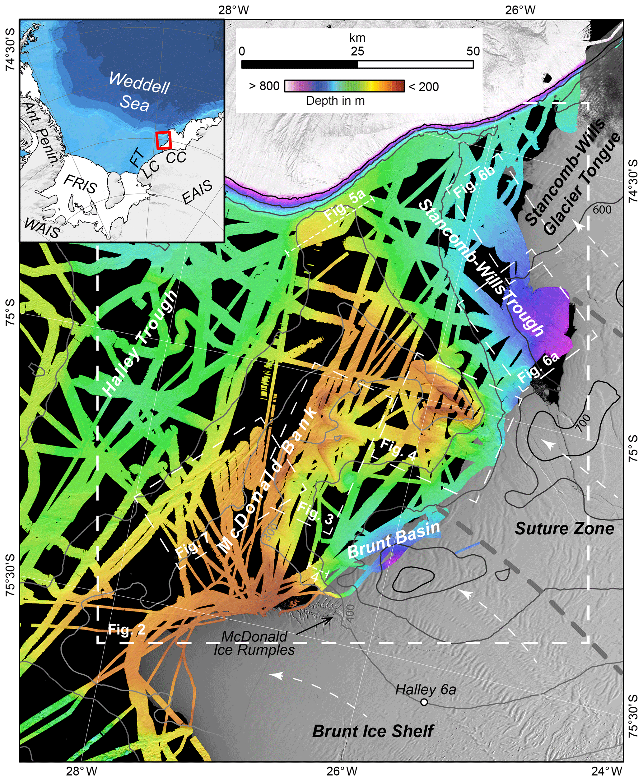
Figure 1Overview map of the study area showing color-coded high-resolution bathymetric data and geographic locations mentioned in the text. Greyscale contour lines are in 100 m intervals from the IBCSO V1.0 data set (Arndt et al., 2013). Background satellite image is from Landsat, courtesy of the US Geological Survey. Locations of other figures and two bathymetric cross profiles, shown in Fig. 5, are indicated by dashed rectangles and lines, respectively. The inset map shows the study area in a broader Antarctic context (background from Arndt et al., 2013). CC stands for Caird Coast, EAIS stands for East Antarctic Ice Sheet, FRIS stands for Filchner–Ronne Ice Shelf, FT stands for Filchner Trough, LC stands for Luitpold Coast, and WAIS stands for West Antarctic Ice Sheet.
Further to the northeast, the Brunt Ice Shelf and the Stancomb-Wills Glacier Tongue form the nearest extant large ice shelf system fed by the EAIS east of Filchner Trough (Fig. 1). Radiocarbon dates from core IWSOE70 3-7-1 recovered just in front of Brunt Ice Shelf (Fig. 2) were interpreted to indicate that this location was not overrun by grounded ice since at least 32.5 ka cal BP (Stolldorf et al., 2012; see Table S2 in the Supplement for correction and calibration of original reported AMS 14C ages). However, an alternative scenario in agreement with the available age constraints suggests that grounded ice overran the core site sometime between 32.5 and 20.7 ka cal BP (Hillenbrand et al., 2014). Sometime after the LGM, the Brunt Ice Shelf is assumed to have been grounded on multiple ”smaller-scale topographic highs” of the McDonald Bank (Fig. 1) that acted as pinning points stabilizing the ice shelf (Hodgson et al., 2019).
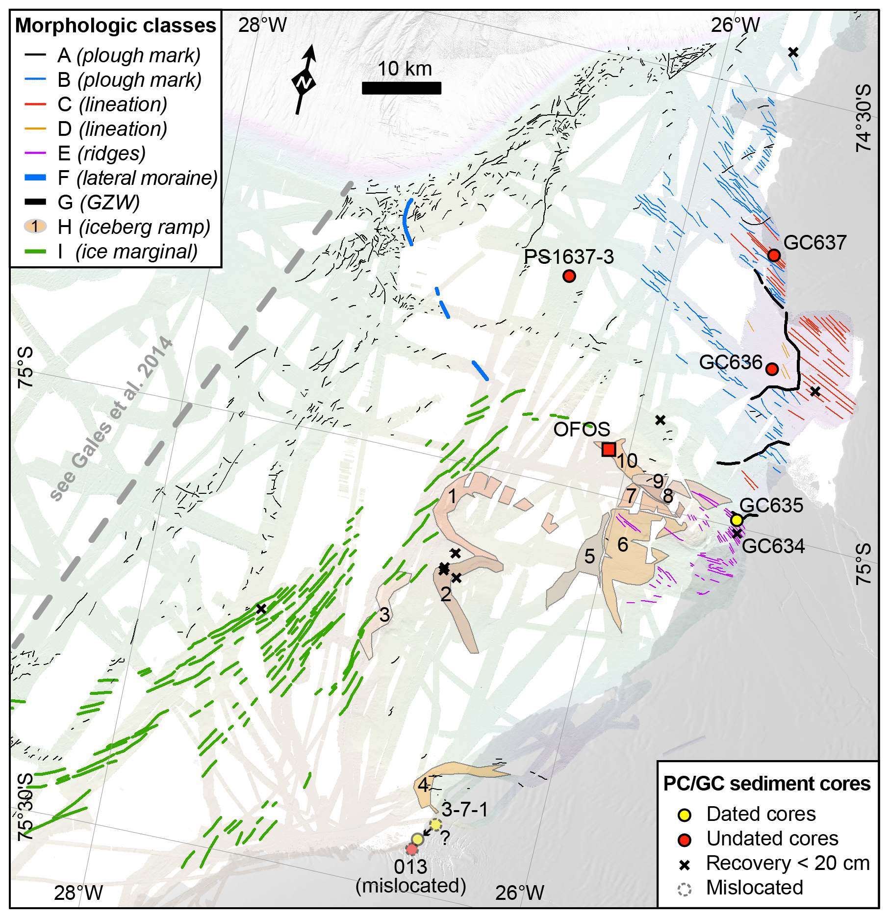
Figure 2Mapped landform classes in the study area; for the location, see Fig. 1. Dots and crosses mark the locations of piston cores (PC) and gravity cores (GCs) (for core site details, see Supplement Table S1). Note that cores 13 and 3-7-1 are presumed to have been mislocated due to inaccurate positioning capabilities in the 1970s, when these cores were retrieved. Core site 3-7-1 is relocated by shifting it to the nearest location in the high-resolution bathymetry data that has the same water depth as measured at the core location. The red square indicates the area where seafloor images were taken by the Ocean Floor Observation System (OFOS; see Fig. S1).
Today, the Brunt Ice Shelf is undergoing significant changes. Recent crevasse and crack formation and their growth may lead to widespread loss of bed contact with the only remaining pinning point, McDonald Ice Rumples (Fig. 1), which may result in rapid ice shelf disintegration in the near future (Hodgson et al., 2019; De Rydt et al., 2018). The permanent British research station Halley (Fig. 1) that had operated continuously since 1956, was relocated in 2017 and subsequently has remained unoccupied during the last three austral winters due to the increased threat of ice shelf disintegration. Glaciological surveys revealed the unusual structure of the Brunt–Stancomb-Wills ice shelf system, which in fact consists of three sectors: Brunt Ice Shelf in the west, Stancomb-Wills Glacier Tongue in the east, and a sector in between these two ice shelves that we here refer to as the “suture zone” (Thomas, 1973; Hulbe et al., 2005). The Brunt Ice Shelf is composed of blocks of meteoric ice of variable sizes (i.e. a number of individual icebergs) that were “cemented” together by sea ice and snow accumulation immediately after their calving (King et al., 2018). In the suture zone, larger tabular icebergs consisting of meteoric ice, up to 25 km across, which we refer to as “ice slabs”, are interspersed with and bound together by thick perennial sea ice, while the Stancomb-Wills Glacier Tongue consists mainly of meteoric ice (Thomas, 1973; Hulbe et al., 2005). Fluctuations in flow velocity of the Brunt Ice Shelf were observed over the last 50 years, most likely resulting from variations in the mechanical connection to the McDonald Ice Rumples pinning point (Gudmundsson et al., 2016). Knowledge of the past development of this ice shelf system and its interaction with pinning points is crucial for a better understanding of its complex nature, which is a prerequisite for modelling and forecasting its future development.
In this study, we investigate the seabed geomorphology of the northeastern WSE shelf offshore from the Brunt Ice Shelf system (Fig. 1), with the purpose of elucidating the imprints of past ice sheet development in this region. Newly mapped submarine glacial landforms in combination with data from recently collected and previously published marine sediment cores provide valuable clues for past ice dynamics and reveal both the ice drainage pattern during the LGM and that slow-flowing, cold-based ice covered a large area. We interpret a set of large seafloor ramps as products of the temporary grounding of meteoric ice slabs that were locked within perennial sea ice and pushed forward by ice shelf motion. During these temporary grounding events, the influence of the growing ramps on ice drainage progressively increased as they acted as pinning points, with the grounded ice slabs buttressing ice flow further upstream.
2.1 Swath bathymetry
Swath bathymetric data were acquired in the study area during 16 Antarctic expeditions with RV Polarstern and RRS James Clark Ross between 1985 and 2018 using various acquisition systems (see Table 1). All bathymetric data were sound-velocity-corrected using conductivity–temperature–depth (CTD) measurements and post-processed to remove outliers in CARIS Hips and Sips or in MB System (Caress et al., 2019; Caress and Chayes, 1996), respectively. All data were exported to ASCII XYZ format and, subsequently, jointly gridded at 25 m resolution in QPS Fledermaus with a weighted moving average algorithm. Bathymetric data were visualized and analysed in QPS Fledermaus and ESRI ArcGIS.
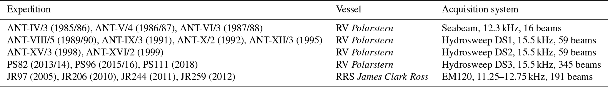
Table 1Expeditions that collected investigated swath bathymetry data within the research area and the used acquisition systems.
2.2 Acoustic sub-bottom profiling
Sub-bottom profiler data were acquired during RV Polarstern expeditions PS82, PS96, and PS111 and during RRS James Clark Ross expedition JR244. On RV Polarstern, a Teledyne RESON Parasound System DS3 (P70) was used to acquire the sub-bottom profiles. This system uses the parametric effect of two high primary frequencies to generate a resulting secondary low frequency, which is used to profile sub-seafloor features. The secondary low frequency was usually set to ∼4 kHz. The resulting beam width of the signal was 4.5∘. On RRS James Clark Ross, a Kongsberg Topographic Parametric Sonar (TOPAS) PS 018 system was used, which works in a similar way. Two primary frequencies around 18 kHz were used to generate a “chirp” secondary transmission pulse with frequencies between 1.3 and 5 kHz. The beam width of the system is 5∘. The penetration depth of both systems depends on the local seafloor characteristics, e.g. when the seabed consists of soft, fine-grained sediments the signal can penetrate down to about 200 m below the seafloor surface with a depth resolution of approximately 30 cm.
2.3 Marine sediment cores
Four sediment cores (GC634, GC635, GC636, and GC637) recovered during RRS James Clark Ross expedition JR244 in March 2011 using a 3 m long gravity corer with a diameter of 110 mm were analysed for this study (Supplement Table S1). In the following sections, we exclusively focus on results from core GC635 (latitude S, longitude W; water depth 494 m; recovery 1.16 m) because it was the only core that provided an age constraint for the time of landform formation. Magnetic susceptibility, P-wave velocity, and wet bulk density were analysed on whole core and split core sections using GEOTEK multi-sensor core loggers (MSCLs) at the British Ocean Sediment Core Research Facility (BOSCORF; Southampton, UK) and at the Department of Geosciences, UiT The Arctic University of Norway (Tromsø, Norway), respectively. After splitting the cores, their working and archive halves were described visually and using smear slides at the British Antarctic Survey (BAS; Cambridge, UK). Sedimentary structures were recorded visually and using X-ray images, which were obtained from the archive halves of the cores with a GEOTEK MSCL X-ray-computed tomograph at UiT (MSCL-XCT; voltage of ∼120 kV; current of ∼225 µA). X-ray images were taken at 2 cm depth resolution to maximize the overlap between images and avoid parallax errors. Sediment colour was recorded on the archive halves visually using Munsell Soil Colour Charts (Munsell Color Company, Inc., 2010) at BAS and using a Jai L-1070CC 3 CCD RGB Line Scan Camera with a resolution of 70 µ m mounted to an Avaatech XRF core scanner at UiT. Shear strength measurements were conducted every 5–10 cm on the working halves of the cores using a handheld shear vane. Discrete 1 cm thick half-round samples at selected depths (intervals from 5 to 20 cm) were taken from the working halves of the cores to determine (i) the water content by weighing the samples before and after freeze-drying and (ii) the grain size distribution (i.e. contents of gravel, sand and mud) by wet- and dry-sieving over 63 µm and 2 mm, respectively. The sand fractions were subsequently investigated under a microscope for analysing the composition of the coarse fraction and picking calcareous microfossils. The picked microfossils were AMS 14C dated using the Mini Radiocarbon Dating System (MICADAS; Synal et al., 2007; Wacker et al., 2010) at the Laboratory of Ion Beam Physics of the Eidgenössische Technische Hochschule (ETH; Zürich, Switzerland). The resulting dates were corrected for a regional marine reservoir effect of 1215±30 years established by the uncorrected 14C age of bryozoans in seafloor surface sediments at site PS1418-1 (see Hillenbrand et al., 2012) and calibrated using the CALIB 7.1 software (Reimer et al., 2013; Stuiver and Reimer, 1993). Previously published AMS 14C dates on benthic foraminifera from piston core IWSOE70 3-7-1 (Anderson and Andrews, 1999; Stolldorf et al., 2012) were corrected and calibrated accordingly (Supplement Table S2).
2.4 Ice slab tracking
Satellite imagery and a map (Fig. 2 of Thomas, 1973) were used to trace the movement of four large meteoric ice slabs enclosed within the suture zone from 1973 to 2017. The map of Thomas (1973) provides the earliest record of their locations. This map was manually georeferenced in ESRI ArcGIS using geographic coordinates from the graticule of the map as reference points. Satellite imagery is from Landsat missions, courtesy of US Geological Survey. Three representative dates were chosen that document the ice slab movements: 30 January 1986 (Landsat 5), 6 January 2000 (Landsat 7), and 4 February 2017 (Landsat 8). These time intervals are sufficient, due to the low ice shelf flow velocity of approximately 500 m a−1.
3.1 Seafloor morphology
An overview of the high-resolution bathymetry data in the study area is shown in Fig. 1. Three major bathymetric features on the shelf are distinguished: two bathymetric depressions located on the innermost shelf that we refer to as Brunt Basin (in the south) and Stancomb-Wills Trough (in the north) and a T-shaped ridge with a SSW–NNE-oriented axis that we refer to as McDonald Bank (Fig. 1). The McDonald Bank separates both depressions from Halley Trough to the west. The ESE-pointing branch of its “T” crossbar partly separates the depressions from each other. This branch also includes the shallowest point on the bank at 196 m water depth. The shallowest mapped part of the bank further south is ∼210 m water depth at a location close to the Brunt Ice Shelf front and about 10 km west of the McDonald Ice Rumples. This water depth matches sub-ice-shelf measurements further east that indicate that the seafloor depth at the McDonald Ice Rumples is about 212 m (Hodgson et al., 2019). The top of the bank elsewhere lies at an average water depth of 260 m. The NW-directed branch of the crossbar at the seaward end of McDonald Bank separates Stancomb-Wills Trough from Halley Trough and forms its deepest part (>300 m water depth, Fig. 1).
The maximum surveyed water depth in Brunt Basin is ∼690 m at a location that is presently covered by the readvanced Brunt Ice Shelf. In contrast to Brunt Basin, Stancomb-Wills Trough extends to the continental shelf edge. The trough increases in depth inshore from ∼500 m water depth at the continental shelf edge to ∼700 m water depth at the most landward surveyed shelf location, approximately 50 km from the shelf edge. Single-beam echo sounder data, acquired at a time when the ice shelf front had a more easterly position, show that deepening continues further inland (Arndt et al., 2013). The slope along the trough axis is ∼0.2∘.
Numerous smaller-scale submarine landforms are present in the study area. We categorize these into nine classes (A–I) based on their morphology. The classes and their morphologic properties are described in detail in Table 2, and their spatial distribution is shown in Fig. 2. Figures 3–7 show their morphologies in detail.
Table 2Morphological classes identified in the swath bathymetric data and their properties.

The most prominent landforms in the study area are 10 ramp-shaped features of Class H (Figs. 3, 4). Their shapes vary, but generally their steep flanks face towards the west. Ramps 1–4, located on the eastern side of McDonald Bank, are crescent-shaped and have a width of about 8–10 km at their open ends and crest widths of about 3 km (Fig. 2, 3). In contrast, ramps 5–10 lack a clear crescent shape (Fig. 4). In cross-profiles, ramps 1–10 appear to have a shape similar to that of the wedges of Class G (Fig. 5b, c, and d), but the ramps appear in a different bathymetric setting, outside of a cross-shelf trough. In addition, their front and back-slope angles generally differ from those of the Class G wedges, which have a mean front slope of about 2.5∘ and a mean back slope of only about 0.5∘. In contrast, mean frontal and back slopes of ramps 1–4 are 3–5 and 1.5–2.2∘, respectively (Fig. 5b), and those of ramps 6 and 8–10 are ∼5–8 and 0.7–1∘, respectively. Two exceptions are ramps 5 and 7, which have slopes (front slope ∼2∘ and back slope ∼0.1–0.5∘) similar to those of the Class G wedges. However, both ramps have the same orientations and occur in the same bathymetric setting as the other Class H ramps. Some ramps are superimposed on other ramps, e.g. ramp 9 formed on top of ramps 8 and 10 (Fig. 4), and the northern part of ramp 2 overlies the southern part of ramp 1 (Fig. 3). Many of the ramps have irregular morphologies at their tops, where the seafloor surface undulates with an amplitude of less than 10 m, e.g. ramps 1 and 2 (Fig. 3).
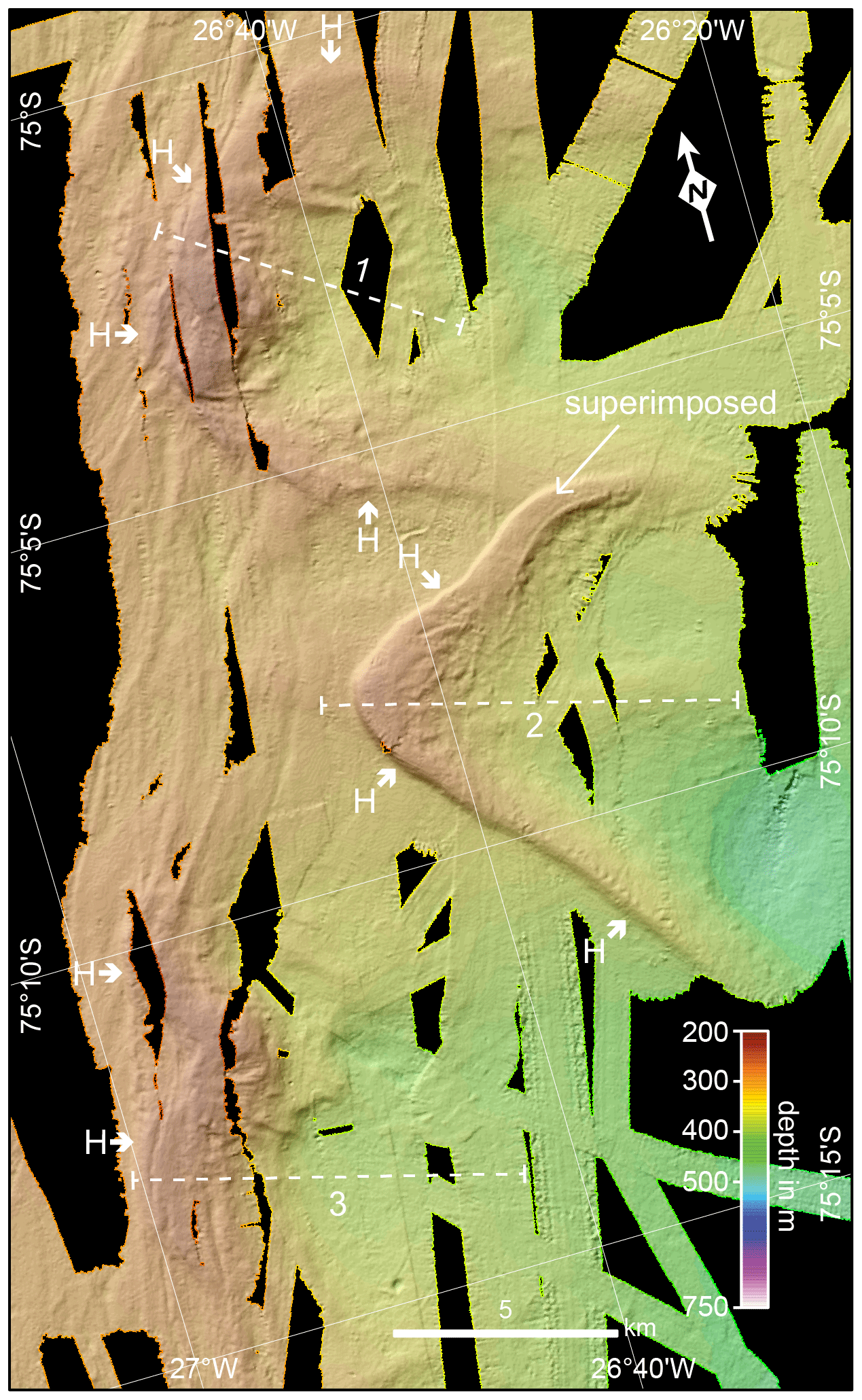
Figure 3High-resolution bathymetric map of the McDonald Bank showing crescent-shaped ramps of Class H (fronts marked by short bold arrows); note that the northern part of ramp 2 superimposes on the southern part of ramp 1, and the top of ramp 2 locally shows irregular seafloor morphology. Dashed numbered lines indicate locations of ramp profiles shown in Fig. 5.
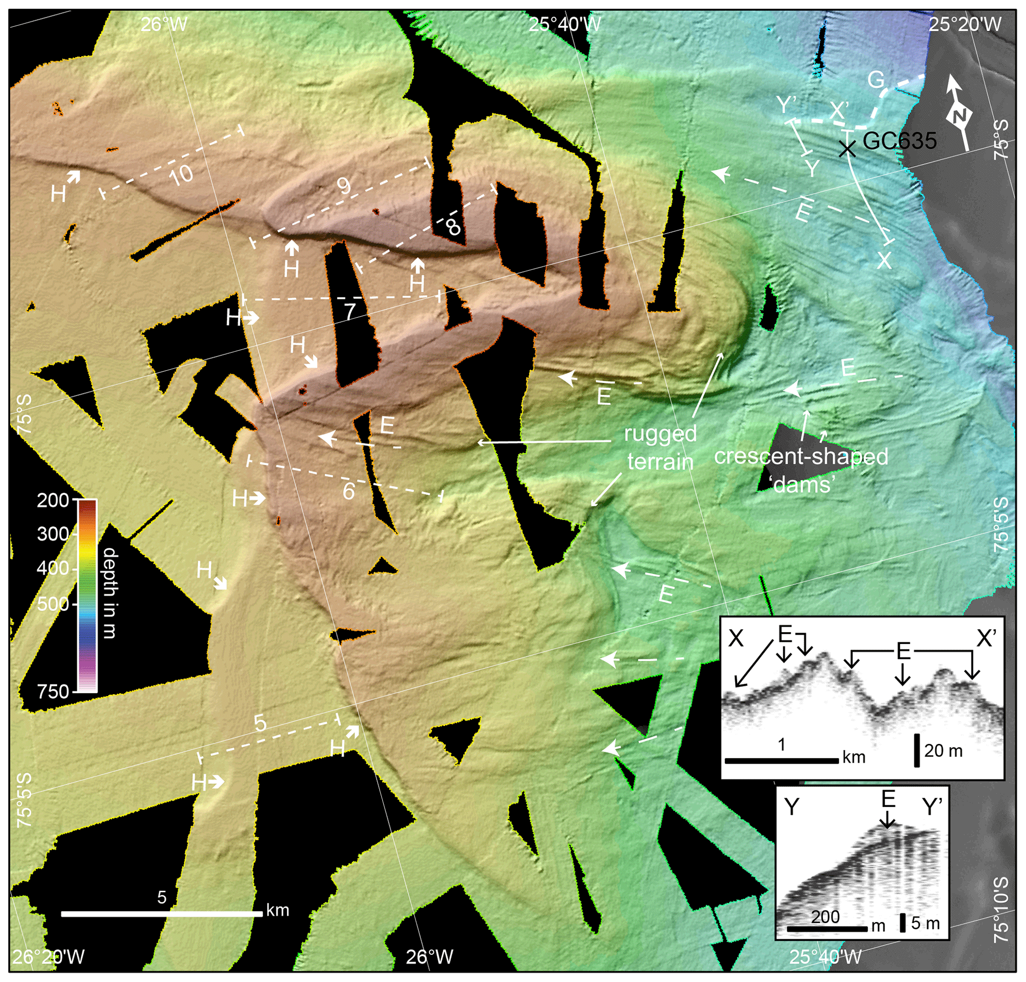
Figure 4High-resolution bathymetric map from the easternmost part of McDonald Bank showing parallel ridges squeezed by and smeared at the base of grounding ice slabs enclosed in perennial sea ice (long dashed arrows, Class E) and wedge-shaped ramps (fronts marked by short bold arrows, Class H). Note the more rugged terrain inshore of the ramps that may reflect outcrops of a mafic intrusion. The bold dashed line marks the front of the innermost grounding-zone wedge (GZW; Class G). The thin dashed numbered lines indicate locations of ramp profiles shown in Fig. 5. Inset figures shows acoustic sub-bottom profiles across Class E landforms.
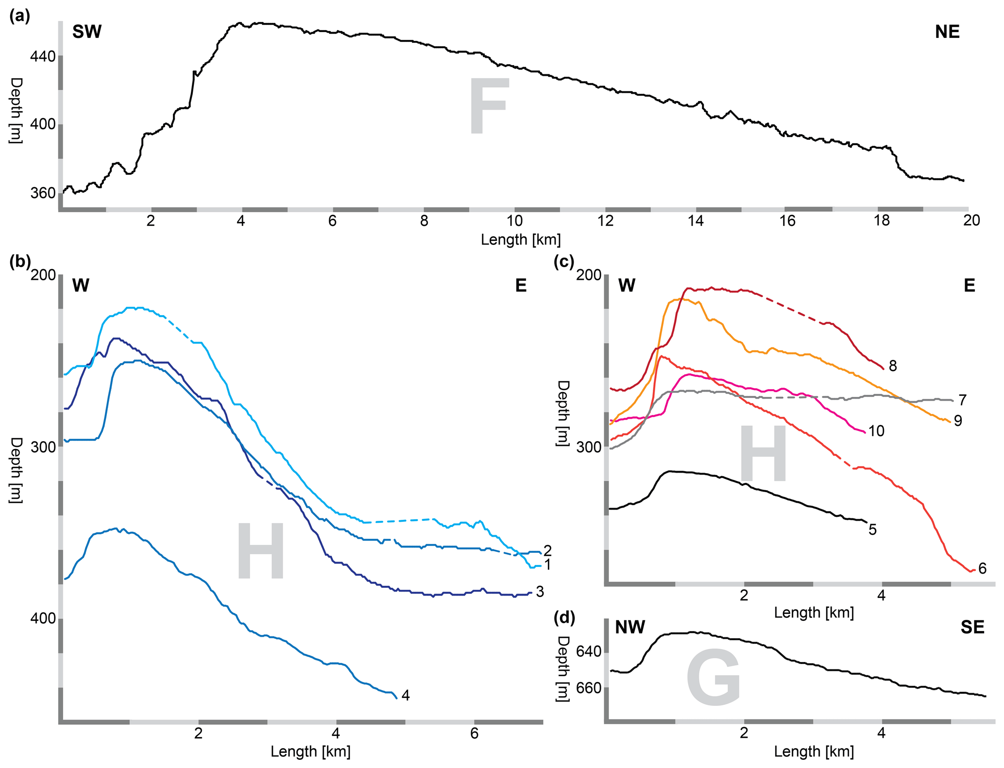
Figure 5Bathymetric profiles across (a) the lateral moraine of morphological Class F, (b) Class H crescent-shaped ramps 1–4, (c) Class H ramps 5–10, and (d) the GZW of Class G in inner Stancomb-Wills Trough. For the locations of profiles in (a), (b), (c), and (d), see Figs. 1, 3, 4, and 6, respectively.
3.2 Core lithology and chronology
Most coring operations carried out in the study area resulted in no or very little recovery, and only six sediment cores with a recovery of more than 20 cm are available (Fig. 2 and Supplement Table S1). Coring operations were unsuccessful, especially on McDonald Bank, i.e. on and close to Class H ramp 2, where four coring attempts failed. Seafloor photographic imagery of Class H ramp 10, acquired by the Ocean Floor Observation System (OFOS) during expedition PS96 at station 10-3 (Piepenburg, 2016), shows that the seafloor is predominantly covered by fine-grained mud (Supplement Fig. S1). Where this fine-grained sediment is absent, a gravel layer is observed, suggesting that the mud forms only a thin and locally absent veneer on top of the gravel layer. Elsewhere, cobbles and boulders are locally present on the seafloor. Gravel layers are difficult to penetrate with conventional coring devices, and together with the observed cobbles and boulders, seriously hamper or even prevent sediment recovery by coring. Under the assumption that the OFOS imagery shows the typical seafloor of McDonald Bank and Class H ramps, this may explain the limited core recovery there.
In Stancomb-Wills Trough, core recoveries were higher than in Brunt Basin and on McDonald Bank (Fig. 2). However, except for neighbouring cores GC634 and GC635 (Fig. 2), calcareous material suitable for obtaining reliable AMS 14C ages was absent (e.g. Hillenbrand et al., 2013). Core GC634 was 14.5 cm long and provided a paired Late Holocene age of ∼4.9 ka cal BP obtained from calcareous benthic and planktic foraminifera (Supplement Table S2). Of all cores with recoveries higher than 20 cm, only the cores GC635 (this study) and IWSOE70 3-7-1 (Anderson and Andrews, 1999; Stolldorf et al., 2012) provided radiocarbon age constraints useful for reconstructing the glacial history of the study area (Supplement Table S2).
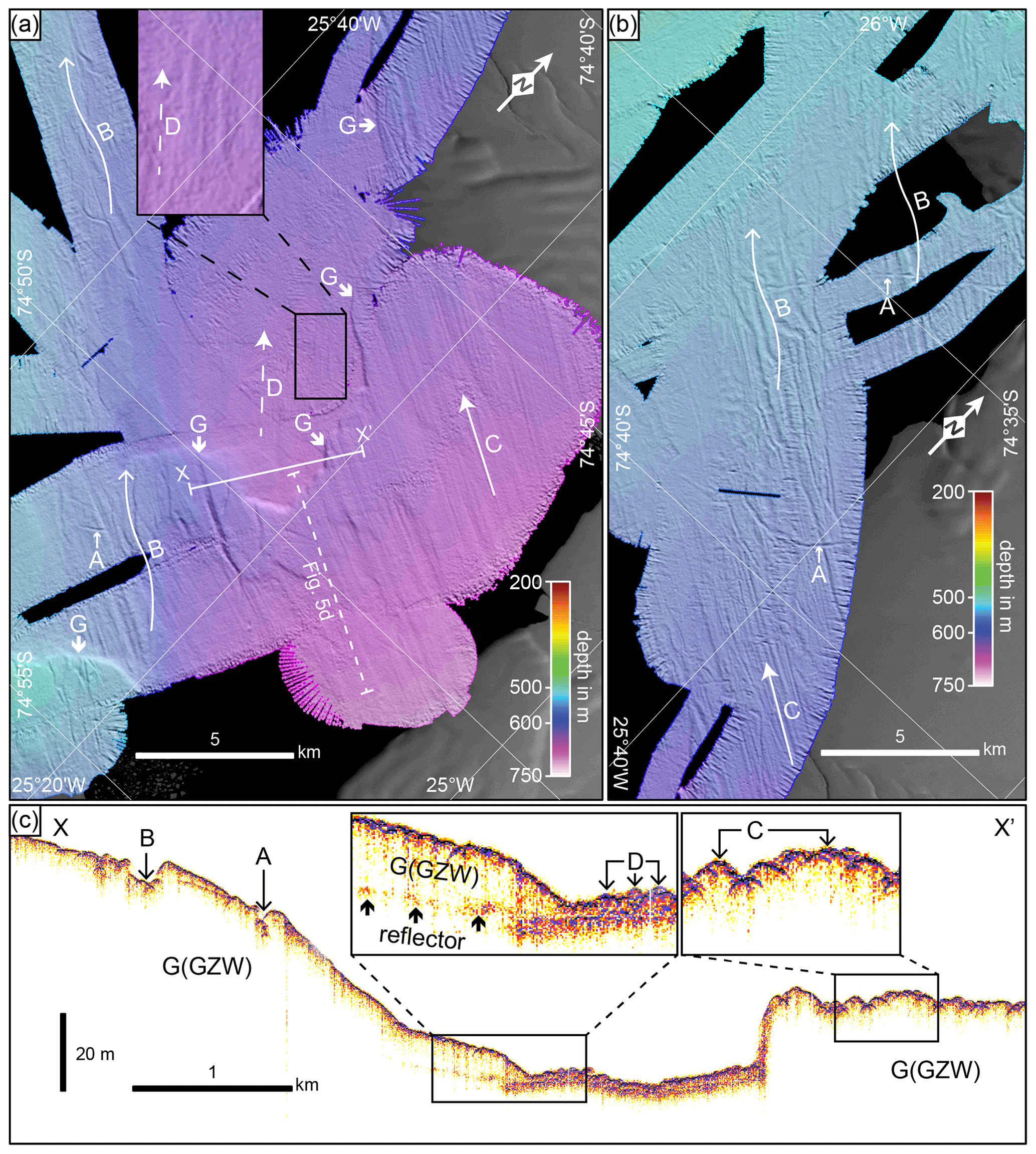
Figure 6High-resolution bathymetric map from the (a) inner and (b) middle Stancomb-Wills Trough showing plough marks eroded by individual icebergs (Class A) and by icebergs pushed by an ice shelf in a preferred orientation (Class B), glacial lineations (long arrows denote Class C, and long dashed arrows denote Class D), and two grounding-zone wedge (GZW) fronts (bold short arrows, Class G). The acoustic sub-bottom profile (c), whose location is shown in (a), crosses landforms of Classes A, B, C, D, and G.
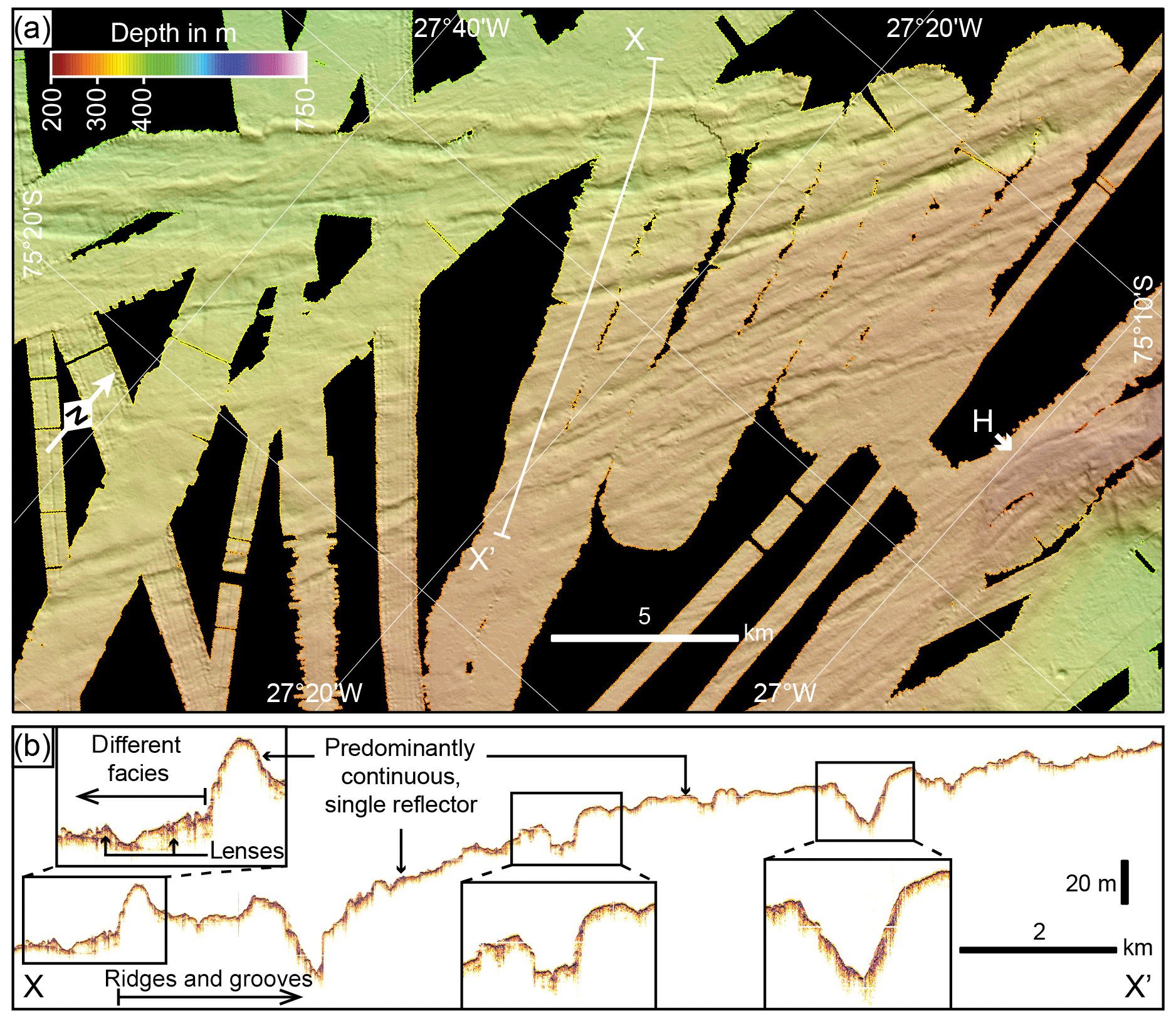
Figure 7High-resolution bathymetric map (a) from the western slope of McDonald Bank showing curvilinear ridges and grooves of Class I that are interpreted as ice marginal landforms. The short bold arrow marks the front of the westernmost Class H ramp. The sub-bottom profile (b) displays the depths of the groove incisions, the lack of penetration of the acoustic signal, and a different acoustic facies northwest of the ridges and grooves.
Core GC635 was retrieved from the southern edge of Stancomb-Wills Trough at a location where Class E landforms are present (Figs. 2 and 4). The sedimentary sequence consists of a thin layer of homogenous sponge-bearing, gravelly, sandy mud near the core top (0–9 cm), overlying a poorly sorted muddy diamicton (9–116 cm) (Fig. 8a). The sand content varies slightly throughout the core. The diamicton is laminated and stratified between 9 and 70 cm core depth and is massive below that. A large pebble is present at 60–65 cm depth influencing the physical properties in this core interval. Shear strength increases and water content decreases down-core within the upper 70 cm of the diamicton, although there is a local minimum in shear strength at 68.5 cm core depth. Increased shear strengths and low water contents characterize the diamicton below 70 cm depth, documenting higher compaction than in the upper part of the diamicton. One bivalve shell fragment (2.7 mg) at 50 cm depth in core GC635 was AMS 14C dated. The sample (laboratory code: ETH-69709) provided an uncorrected age of 10 475±90 14C years and after marine reservoir effect correction and 14C age calibration an age of 10 520±260 cal years BP (Supplement Table S2).

Figure 8Sedimentological parameters and radiocarbon ages from cores in the study area (for the location, see Fig. 2): (a) lithology, shear strength (str.), wet bulk density (WBD), magnetic susceptibility (mag. sus.), grain size composition of the sediment matrix, water content (H2O), facies interpretation, and AMS 14C ages of core GC635 (this study) and (b) lithology and AMS 14C ages of core 3-7-1 (modified from Stolldorf et al., 2012). For the given ages, see Table S2.
4.1 Iceberg plough marks (Class A)
We interpret the single linear to curvilinear furrows with random orientations predominantly occurring on the outer shelf part of Stancomb-Wills Trough as iceberg plough marks. Iceberg plough marks are common seafloor features on the Antarctic continental shelf (e.g. Gales et al., 2016; Lien et al., 1989). Where iceberg keels run aground they rework the upper few metres of the seabed, forming a berm of iceberg-turbated sediments at the plough mark edge (Fig. 6c). Pre-existing seafloor landforms may have been eradicated in areas with abundant plough marks.
4.2 Iceberg plough marks with preferred orientation (Class B)
Class B landforms have similar morphological attributes to the iceberg plough marks of Class A (see Table 2 and Fig. 6). However, in contrast to the latter, they have a preferred, although not perfectly parallel, orientation. We interpret these features as plough marks carved into the seafloor by numerous single-keeled and probably some multi-keeled icebergs. The direction of these plough marks is aligned sub-parallel to the modern and past ice sheet and ice shelf flow directions, and their occurrence is restricted to an area within Stancomb-Wills Trough landward of the continental shelf edge, with the water depths of the aligned plough marks (500–600 m) being greater than that of the shelf edge (∼500 m and less). Icebergs eroding these features could not have drifted into the area from elsewhere and thus must have originated from an ice shelf present in Stancomb-Wills Trough. We assume that calved icebergs were pushed by the ice shelf front in its flow direction, probably enclosed within a newly formed sea ice melange that held them in place. If the drafts of the iceberg keels were sufficiently deep, this resulted in plough marks with preferred orientation as observed in our data. A similar process has previously been suggested for parallel multi-keeled iceberg plough marks in the outer shelf sections of Filchner Trough in the WSE (Larter et al., 2012) and Cosgrove-Abbot Trough in the easternmost Amundsen Sea embayment, West Antarctica (Klages et al., 2015).
4.3 Mega-scale glacial lineations (Class C and D)
The parallel, linear ridges of Classes C and D located in the deeper parts of the Stancomb-Wills Trough resemble mega-scale glacial lineations (MSGLs). MSGLs are common features in formerly glaciated areas and form along the direction of ice flow at the base of fast-flowing ice streams (Clark, 1993; King et al., 2009) within a deformable sediment layer (Alley et al., 1986; Ó Cofaigh et al., 2005; Reinardy et al., 2011). The orientation of Class C and D MSGLs differs by 15–25∘ (Figs. 2, 6), and the amplitudes of Class D MSGLs are smaller than the amplitudes of Class C MSGLs. This suggests that the two classes of MSGLs were produced at different times, with the more subdued Class D MSGLs located further offshore being older than the Class C MSGLs. This is supported by acoustic sub-bottom profiler data: Class D lineations are characterized by a thicker or more diffuse top reflector than the more distinct top reflector of Class C lineations, which could indicate a thin sedimentary drape on Class D lineations that was deposited when the Class C lineations were being formed (Fig. 6c).
4.4 Squeezed and smeared ridges formed by grounded tabular icebergs enclosed in perennial sea ice (Class E)
The elongated Class E ridges are present only within the most landward shelf area at the base and locally on top of the ice shelf proximal wedge-shaped ramps of Class H (Figs. 2 and 4). The amplitude and shape of the ridges strongly resemble those of MSGLs, especially locally where some of them occur as sets of parallel ridges. However, unlike the MSGLs of Classes C and D, all the ridges of Class E are curvilinear rather than linear, or even have a more irregular, sinuous shape, and their directions in general are more variable. Occasionally, the ridges also terminate in a crescent-shaped “dam” (Fig. 4), similar to terminal berms of icebergs plough marks (e.g. Lewis et al., 2016). Sub-bottom profiler data across the ridges reveal their formation in an acoustically transparent sediment layer on top of a strong, continuous sub-bottom reflector (insets of Fig. 4). Incisions into the sub-bottom reflector are absent. This contradicts an interpretation as a typical iceberg plough mark berm that usually is formed by material excavated from the plough mark centre (for example, see Classes A and B in Fig. 6c). However, the smeared impression of the features may suggest a similar kind of formation.
Considering all morphologic properties of the ridges, these are neither typical glacial lineations nor typical iceberg plough marks. Their proximity to wedge-shaped ramps of Class H and their orientation in dip direction of these ramps might indicate that the formation process of these landforms is related. We hypothesize that these ramps were formed by temporary grounding of large meteoric ice slabs enclosed within perennial sea ice in the suture zone between Brunt Ice Shelf and Stancomb-Wills Glacier Tongue (see below). In agreement with this hypothesis, we suggest that the ridges of Class E were formed by seafloor sediments being squeezed into basal crevasses in the ice slabs when these ran aground. Subsequently, these sediments were “smeared” into the direction of the movement of the ice slabs. A source for these sediments may be the till layer, in which the MSGLs (Class C and D) in Stancomb-Wills Trough had formed (Fig. 6c). This would also explain why these ridges are only present close to the trough, where such soft till substrate is available (Fig. 4), but are absent on the ramps further to the south in Brunt Basin (Fig. 3), i.e. at a location distal from the MSGLs.
4.5 Lateral marginal moraine (Class F)
The wedge-shaped bank on the outer shelf that forms the southwestern flank at the seaward end of Stancomb-Wills Trough is a lateral moraine. Batchelor and Dowdeswell (2016) reviewed 70 lateral moraines described in previous studies and identified two different types that can be distinguished by their geometry: lateral shear moraines and lateral marginal moraines. Lateral shear moraines are either roughly symmetrical or have a steeper trough-facing flank in cross section. In contrast, lateral marginal moraines are wedge-shaped in cross profile with a steeper flank facing away from the trough. They are effectively grounding-zone wedges formed by spreading of the downstream part of an ice stream that was not laterally constrained. We observe the latter in Stancomb-Wills Trough (Fig. 5a) indicating that the Class F feature formed as a lateral marginal moraine.
4.6 Grounding-zone wedges (Class G)
The three wedge-shaped mounds of Class G located in the inner part of Stancomb-Wills Trough (Figs. 4, 6a, 6c) are interpreted as grounding-zone wedges (GZWs). GZWs are ice-marginal deposits formed at the transition from a grounded ice stream to a floating ice shelf, the so-called grounding zone (e.g. Alley et al., 1989; Batchelor and Dowdeswell, 2015). These landforms are produced by high subglacial sediment supply under fast-flowing ice streams to their termini during phases of grounding-line still-stands (Ó Cofaigh et al., 2008). A GZW typically has a steep front and a gentle back slope due to the restricted accommodation space beneath the ice shelf close to the grounding line. The mapped MSGLs (Classes C and D, Figs. 2, 6) give evidence for past ice streaming in Stancomb-Wills Trough that facilitated high subglacial sediment transport. The northernmost of the three identified GZWs is located in the central part of Stancomb-Wills Trough, with sub-bottom profiler data indicating that the GZW was deposited on top of a prominent reflector, most likely representing a pre-existing seafloor surface (left inset in Fig. 6c). The other two GZWs, located further upstream, are only mapped at the southern side of the trough but likely continue into the trough centre that is presently ice shelf covered. The observed set of GZWs indicates that at least three phases of grounding-line still-stands occurred within the trough during the retreat of the paleo-ice-stream.
4.7 Iceberg ramps (Class H)
On first examination, the wedge-shaped ramps of Class H show similarities to GZWs, but their mean front and back slopes are steeper, with the exceptions of ramps 5 and 7 that also have similar crest heights to the northernmost GZW in Stancomb-Wills Trough (see Fig. 5b, c, d). In addition, the location of ramp 10 at the southern edge of Stancomb-Wills Trough raises the possibility that this ramp was deposited as a lateral marginal moraine (Class F) by the paleo-ice-stream when it flowed within the trough. However, the close proximity, orientation, and morphological similarity to the other ramps points to formation of ramps 5, 7, and 10 by the same process as the other Class H ramps. Nevertheless, we cannot rule out the possibility that ramps 5, 7, and 10 were formed by a different process, i.e. as a GZW (ramps 5 and 7) or as a lateral marginal moraine (ramp 10).
Indications for the presence of a paleo-ice-stream south of Stancomb-Wills Trough at the location of the ramps are lacking. Only such an ice stream would have been able to supply large volumes of subglacial sediment to the grounding zone fast enough to build up a GZW (Batchelor and Dowdeswell, 2015). Glacial lineations, which would indicate fast ice flow (e.g. King et al., 2009), are absent, both on the tops and in front of Class H ramps (Figs. 3, 4). In addition, the ramps are located outside a cross-shelf trough, the typical topographical setting of GZWs, where repeated channelized ice streaming over several glacial stages deeply eroded the seabed, providing a plentiful source of sediment (e.g. Livingstone et al., 2012). Consequently, we exclude the possibility that the ramps were formed as GZWs.
The most prominent ramps are the crescent-shaped ramps 1–4 at the eastern edge of McDonald Bank (Figs. 2, 3). In contrast to ramps 5–10, which exhibit multiple examples of superimposition, of the four remaining ramps only ramps 1 and 2 overlap marginally. Hence, ramps 1–4 probably are more suitable for understanding the process responsible for their formation.
Arcuate terminal moraines located at fjord mouths in the Arctic have heights comparable to the ramps on the northeastern WSE shelf and have a similar crescent shape, e.g. in Raudfjorden, northern Svalbard (Ottesen and Dowdeswell, 2009), or in Scoresby Sund, eastern Greenland (e.g. Arndt, 2018). The crescent shape of these terminal moraines is a result of diverging ice flow due to disappearing lateral topographic constraints at the fjord mouth. In contrast, the discussed ramps in our study area are located in areas without such topographic constraints. Therefore, we conclude that, even though some morphological similarities exist, the ramps are features other than terminal moraines.
Hill–hole pairs observed on the Norwegian continental shelf have similar arcuate shapes and dimensions to ramps 1–4 (Rise et al., 2016). Rise et al. (2016) suggest that these hill–hole pairs occur in areas of slow-flowing ice, which locally froze to the bed, ripped up seafloor sediment, and subsequently redeposited the sediment “lump” further downstream and glacitectonically deformed the deposit. A similar glaciological regime of slow ice flow probably existed in the area of the Class H ramps, which is characterized by the absence of glacial lineations and a location outside a cross-shelf trough. The holes of the hill–hole pairs on the Norwegian shelf mark the locations from where the sediment hills were excavated and are characterized by clearly distinguishable depressions of rugged terrain that are about 15 m deeper than the surrounding seafloor. Such delineated holes or depressions are absent upstream from the ramps identified in our study (Figs. 3, 4). However, bathymetric profiles across ramps 1–3 show that their back slopes have a “listric” topography, becoming relatively flat beyond about 5 km upstream of their fronts (Fig. 5b). This may indicate that some kind of excavation process was active at this location, as the slope gets steeper towards the crest of the ramp. However, the seafloor surface in these probably excavated areas is smooth rather than rugged, whilst a distinct boundary typical for the depressions of the hill–hole pairs on the Norwegian shelf is missing. Furthermore, hill–hole pairs with a dimension of more than 5 km seem to be rare, with the ones of the Norwegian shelf being the only published examples. In contrast, hill–hole pairs documented in the Antarctic are smaller (Klages et al., 2013, 2015; Larter et al., 2019). Therefore, we conclude that the process of cold-based hill–hole pair formation is unlikely to explain the formation of the Class H ramps.
Landforms on the western flank of Crary Bank in the Ross Sea were described as “wedges pinned on seamounts” and were interpreted to represent grounding-line retreat positions of a regrounded ice shelf (Fig. 5b in Greenwood et al., 2018). These features share a similar geographical setting to the Class H ramps as both are located on the slope of a shallow bank that faces the grounded ice sheet and have similar heights. Greenwood et al. (2018) observed subtle lineations on top of the wedges in the Ross Sea. Such lineations are absent from the tops of the Class H ramps on the northeastern WSE shelf. The only lineations observed here are the curvilinear ridges of Class E, which exclusively occur at the base of the easternmost ramps. The Crary Bank wedges are mostly ≤4 km across, with only one elongated feature extending over a length of approximately 7 km, so they are generally smaller than the Class H ramps. Unlike the ramps, the features in the Ross Sea are circular rather than crescent shaped. In addition, their tops are flat over a distance of about 2 km. In contrast, bathymetric profiles across Class H ramps show that their tops are convex (Fig. 5b, c). The Crary Bank seamounts are located in the volcanically active region of the Terror Rift and were interpreted as subglacial volcanic features (Lawver et al., 2012). The northeastern WSE shelf, however, lacks any Cainozoic volcanic activity. The morphological differences and the absence of recent volcanic activity thus suggest a different formation process for the Class H ramps.
The smoothness of the seafloor at and around most of the ramps suggests that it consists of sedimentary material. In contrast, the rugged terrain described inland of ramp 6 may represent a bedrock substrate, which geographically coincides with the inferred location of a large mafic intrusion (Jordan and Becker, 2018). When drifting icebergs run aground on a sedimentary seafloor substrate with sufficient force, they produce plough marks with berms on either side (see also Class A landforms). If an iceberg encounters seafloor substrate where drag associated with ploughing increases to match the force pushing the iceberg into the seabed, the movement of the iceberg slows down drastically and eventually stops, with the iceberg keel producing a terminal berm that consists of the pushed substrate at its front (e.g. Lewis et al., 2016). A statistical investigation from the eastern Amundsen Sea embayment shelf shows that most of the observed iceberg plough marks there have widths of 40–300 m and incision depths of less than 20 m (Wise et al., 2017), with iceberg plough mark berm heights typically being about 50 % of the incision depths. Hence, their dimensions are significantly smaller than those of the Class H ramps (more than a magnitude narrower and less than 20 % in height), suggesting that the ramps are morphological features other than typical iceberg plough marks.
Nevertheless, the crescent shape of ramps 1–4 resembles the shape of a typical terminal iceberg berm well but at a considerably larger scale (Fig. 3). Jakobsson et al. (2011) proposed that the largest iceberg berms and plough ridges in Pine Island Trough in the eastern Amundsen Sea were created by an iceberg melange resulting from the break-up of an ice shelf. These landforms and their proposed formation process are, however, not a blue print for the Class H ramps in front of the Brunt Ice Shelf due to significant differences. The Class H iceberg ramps are approximately 5 times larger than the largest Pine Island Trough landforms. Furthermore, they occur outside of a prominent paleo-ice-stream trough (characterized by abundant presence of MSGLs), and their occurrence on a bed interpreted as having been covered by cold-based ice points towards low availability of sediment (i.e. lack of soft till). Nevertheless, the suggested formation process for the Pine Island Trough landforms indicates that larger-scale landforms may be created by icebergs if external forces, in this case the pressure of an iceberg melange, are active.
The structure of the Brunt–Stancomb-Wills ice shelf system and reconstructed ice flow orientation changes indicate that larger icebergs enclosed in perennial sea ice melange driven by greater force likely grounded in the area in the past. Therefore, we assume that these enclosed icebergs once grounded with sufficient force to form the Class H ramps by deformation of material on the seafloor. At the same time, these ramps would have become increasingly active as pinning points buttressing ice flow further upstream. We outline the glaciological circumstances and the hypothesized formation mechanism of the Class H ramps in more detail in the discussion.
4.8 Ice-marginal ridges and grooves (Class I)
The slightly curvilinear ridges and grooves of Class I occur only on top and at the western flank of McDonald Bank (Fig. 7). Their orientation is at a high angle or even perpendicular to flow directions indicated by the long axes of the nearby paleo-ice-stream troughs, i.e. Halley Trough to the west and Stancomb-Wills Trough to the north. Orientations of MSGLs in the latter suggest an inter-ice-stream environment. For such an environment, most of the morphological attributes of the Class I ridges (amplitude, width, length, orientation) indicate that these features are retreat moraines as observed in other inter-ice-stream areas of previously glaciated continental shelves (Ottesen and Dowdeswell, 2009).
Sub-bottom profiles across the ridges and grooves predominantly show a continuous single seafloor–surface reflector, locally incised by very small (approx. 1 m and less) furrows (Fig. 7b). Sub-bottom reflectors are absent. In contrast, the deeper seafloor of Halley Trough directly northwest of the ridges and grooves shows a different acoustic facies (left zoom-in of Fig. 7b). Here, acoustically transparent lenses overlie a continuous, flat sub-bottom reflector. As MSGLs are apparently absent in Halley Trough (this study; Gales et al., 2014), we do not consider that these acoustically transparent lenses correspond to a soft till layer like that observed in other Antarctic paleo-ice-stream troughs (e.g. Ó Cofaigh et al., 2005; Livingstone et al., 2012). In contrast, several iceberg plough marks are mapped in this area (Fig. 2). Accordingly, we interpret the transparent lenses in Halley Trough as deposits resulting from iceberg turbation that were formed by ploughing of iceberg keels through relatively soft sedimentary strata. The change in acoustic facies towards the ridges and grooves in the southeast indicates that different environmental conditions prevailed, i.e. with grounded ice covering the seafloor at and to the southeast of the ridges and grooves but absent from Halley Trough.
It remains, however, unclear why the Class I features consist of ridges, typical for retreat moraines, and grooves. Nevertheless, based on the reasons outlined above, we suggest that these ridges and grooves were formed close to the terminus of slow-flowing ice at some time in the past. Remarkably, some of the grooves are incised within ramps 1 and 3, implying that they must have formed after these Class H ramps.
5.1 Iceberg ramp formation
The comparison of Class H features to other similar landforms described in the literature does not allow the identification of an unequivocal formation process for these landforms (see Sect. 4.7). Here, we propose a ramp formation mechanism that is strongly linked to the unusual structure of the Brunt–Stancomb-Wills ice shelf system and past ice flow orientation changes, resulting in moulding of these ramps into McDonald Bank by large ice slabs enclosed within the suture zone of the ice shelf system.
The Brunt Ice Shelf has an unusual ice shelf structure because, unlike other ice shelves, the inland ice here loses its structural integrity when flowing across the grounding line and breaks apart into icebergs, which subsequently are “glued” together by freezing sea ice and drifting snow to form the ice shelf (King et al., 2018). A similar process is also active in the suture zone located between the slower-flowing Brunt Ice Shelf and the faster-flowing Stancomb-Wills Glacier Tongue (Fig. 1, Thomas, 1973; Gudmundsson et al., 2016). The different velocities result in shearing and the production of large ice slabs just downstream of the grounding line. Satellite imagery shows that these icebergs, enclosed within the thick sea ice and snow drift today, have lateral dimensions from 6 to 35 km (Fig. 9a), which is within the size range of the observed ramps. Today, the icebergs trapped within the multiyear sea ice are up to about 300 m thick, as shown by the Bedmap2 data set (Fretwell et al., 2013) and a single transect of Operation IceBridge (http://www.nsidc.org/data/icebridge, last access: 16 June 2020). Accordingly, the modern draft of these icebergs is about 275 m. Iceberg keels probably reached greater water depths during glacial stages when sea level was lower and ice sheets were probably thicker. Hence, we assume that the water depths of 200 to 440 m, at which the ramps occur today (Fig. 5b and c), are within the range of past iceberg keel drafts.
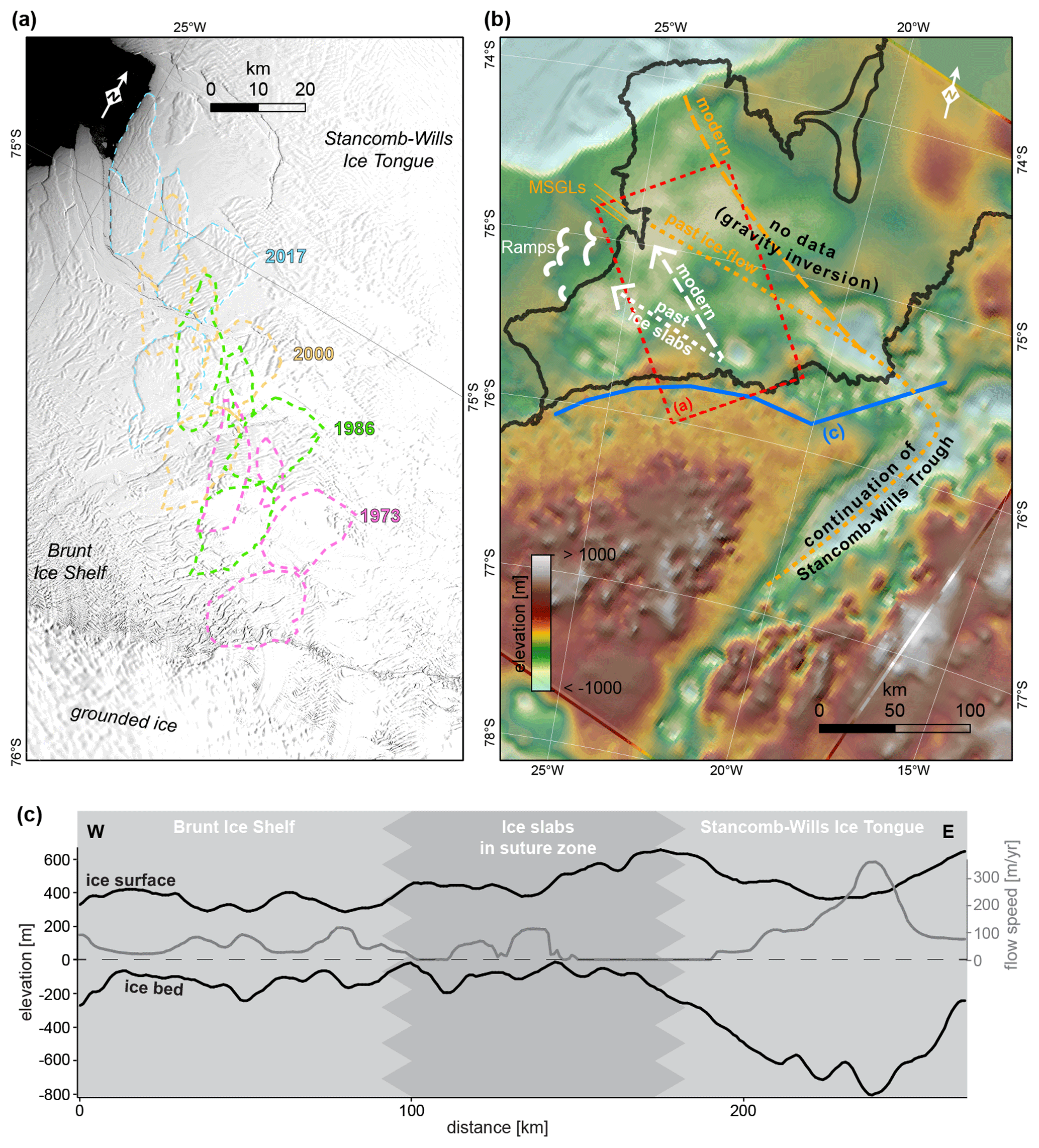
Figure 9(a) Landsat satellite image (courtesy of the US Geological Survey) showing the location of four large ice slabs enclosed within perennial sea ice in February 2017 and their trajectory since 1973. (b) Map of sub-ice-shelf bathymetry, inferred from gravity inversion in the central part (Hodgson et al., 2019), with locations of mega-scale glacial lineations (Class C and D) and iceberg ramps (Class H). Furthermore, the main trajectory of large ice slabs under modern conditions (see a) and the assumed main trajectory of paleo-ice-slabs at the time of ramp formation are shown. The inferred direction of paleo-ice-streaming supports the continuation of Stancomb-Wills Trough into a modern subglacial trough. (c) Profiles of ice surface, bedrock topography (Fretwell et al., 2013), and ice flow speed (Mouginot et al., 2017) inshore of the grounding line (for the location, see b). Note the high flow velocity in the deepest section flowing into Stancomb-Wills Ice Tongue and the shallow bedrock altitude with thick ice in the suture zone forming the large ice slabs.
Today, the transport direction of the enclosed icebergs is approximately towards the northwest, providing an iceberg trajectory that passes just about 10 km north of the northernmost ramps (Fig. 9a, b). Under glacial time conditions, however, different ice flow patterns may have redirected the trajectory of the enclosed icebergs towards the ramps, most likely as a result of increased ice flow through Stancomb-Wills Trough. The MSGLs mapped in Stancomb-Wills Trough (feature classes C and D) indicate that such increased outflow occurred in the past and that the ice flow direction was different. The ice flow direction change is, furthermore, supported by the subglacial topography further upstream. A large NNE-directed subglacial trough is located upstream of the grounding line of Stancomb-Wills Glacier Tongue (Fig. 9b, Fretwell et al., 2013). This trough is on average 40 km wide and 700 m deep and extends at least 200 km upstream of the grounding line, with today's ice flow in its centre exceeding velocities of 300 m a−1 close to the grounding line (Mouginot et al., 2017). Ice flowing through this trough today feeds into the Stancomb-Wills Glacier Tongue that flows in an approximately northeasterly direction (Fig. 9b). Upstream of the suture zone and upstream of Brunt Ice Shelf similar subglacial troughs and ice flow velocities are lacking (Fig. 9c). This indicates that the subglacial trough upstream of the Stancomb-Wills Glacier Tongue is the main gateway for ice discharge at present and probably acted as such during times of an extended EAIS, too. The MSGLs mapped in Stancomb-Wills Trough were formed during these times and their orientation is approximately WNW–ESE, i.e. they point upstream in the direction of where the subglacial trough reaches the modern grounding line. Despite a major data gap underneath the ice shelf, the latest sub-ice-shelf bathymetry model calculated from gravity inversion (Hodgson et al., 2019) indicates that this subglacial trough probably is a continuation of Stancomb-Wills Trough. These findings suggest that past ice flow in the trough area was redirected anticlockwise in a WNW direction and thus forced the trajectory of large icebergs enclosed in the suture zone also into a WNW direction, i.e. exactly into the direction of the ramps on the eastern flank of McDonald Bank (Fig. 9b).
The morphological properties of the ramps support a formation process by iceberg grounding and subsequent moulding. Apart from the fact that their shape resembles that of terminal berms of iceberg plough marks but at a larger scale, at least some of the ramps show indications of superimposing by neighbouring ramps. One example is the northern berm of ramp 2, which superimposes the southern berm of ramp 1 (Fig. 3). Another example is ramp 9, whose flank overlies the edges of ramps 8 and 10 (Fig. 4). In addition, this ramp shows a curvilinear long axis that is aligned to the direction of modern flow of the Brunt Ice Shelf (De Rydt et al., 2018). Superimposed iceberg berms are observed frequently on heavily scoured shelves of glaciated continental margins (e.g. Bjarnadóttir et al., 2016). The areas of irregular seafloor morphology on top of some ramps may be explained by the iceberg formation scenario as well. The amplitude of such irregularities is <10 m, which is well within the range of usual iceberg ploughing. The irregular surface was probably formed at the time when the large iceberg broke apart, as this break-up would have resulted in locally variable pressure exerted onto the ramps by free floating, grounded, and capsizing iceberg fragments.
Even though until now seafloor landforms of similar dimensions, shapes, and in similar bathymetric settings have not been observed and a recent equivalent of the formation process has not been reported, the sum of the observations detailed above supports the hypothesis that the ramps were formed by icebergs enclosed in a perennial sea ice melange. In Fig. 10, we illustrate the proposed formation process of a hypothetical, roughly 3 km long ramp in an about 6-year-long time series based on the modern-day ice shelf flow velocity of approximately 500 m a−1. The illustration also provides a concept of stresses that we infer were active during ramp formation and which would have affected the integrity of an ice slab and surrounding perennial sea ice. These stresses comprise back stress caused by friction induced by ice slab grounding and gravitational stress caused by the progressive “jacking up” of the ice slab front. At a certain stage, these stresses may reach thresholds leading to a stress release by fragmentation of the sea ice melange or fracturing of the ice slab due to the cliff height at its front edge exceeding its yield strength.
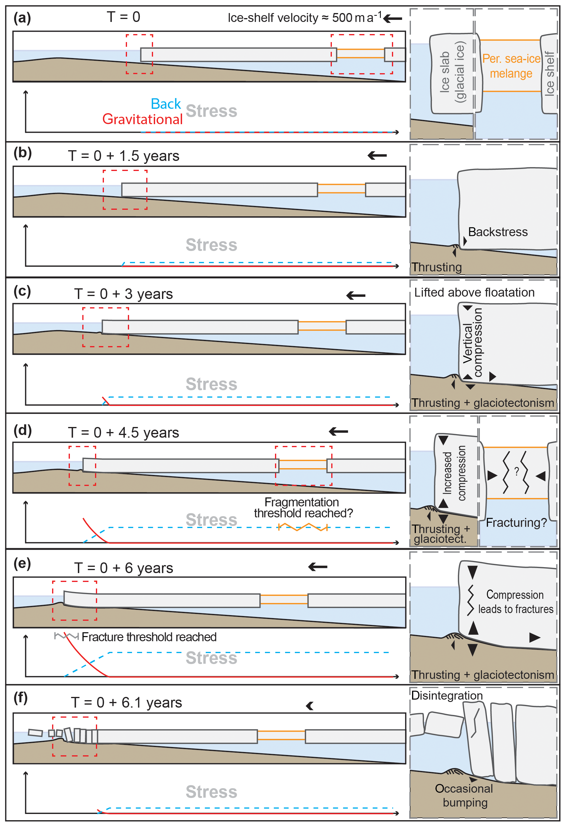
Figure 10Sketch of the proposed iceberg ramp (Class H) formation process, including a conceptual graph of stresses active during formation, with time estimates based on modern ice shelf flow velocity of about 500 m a−1. (a) Setting before the contact of the ice slab with the seafloor. (b) Initial contact of the ice slab with the seafloor leads to seaward directed thrusting of sediments at the front of the slab and build-up of back stress within the ice slab further upstream of the point of contact. (c) The front of the ice slab is “jacked up” causing gravitational stresses and vertical compression within the ice slab; continued thrusting of the sediments combined with their compression leads to glaciotectonism, and back stress within the slab increases further. (d) Continued uplift of the slab front increases stresses, with the back stress probably exceeding a threshold that causes the fragmentation of the perennial sea ice melange. (e) Gravitational stress reaches a level that causes fracturing of the ice slab front. (f) The ice slab disintegrates into smaller icebergs, which capsize and occasionally “bump” into the top of the newly formed ramps when they drift seawards.
5.2 Glacial reconstruction of the northeastern Weddell Sea embayment
5.2.1 Chronological constraints
The absolute chronology of ice sheet history in the study area is poorly defined by only two existing chronological constraints from marine sediment cores (Fig. 8, Table S2): one is from core GC635, which was recovered from the southern edge of Stancomb-Wills Trough, and the other is from core 3-7-1, which was collected from the eastern flank of McDonald Bank near the present Brunt Ice Shelf front (Fig. 2; Stolldorf et al., 2012; Anderson et al., 1980, 1981).
We assign the sediments recovered in core GC635 to three different lithological facies (Fig. 8a): the gravelly sandy mud between 0 and 9 cm core depth bears abundant sponge spicules, indicating deposition of this facies under glaciomarine and potentially (seasonal) open marine conditions. The lamination and stratification of the predominantly terrigenous diamicton from 9 to 70 cm suggests that this facies was also deposited in a glaciomarine setting, which is supported by the presence of a bivalve shell fragment. The predominantly terrigenous composition of this facies, together with the absence of bioturbation, points towards deposition underneath an extended ice shelf or under perennial sea ice cover. In contrast, the purely terrigenous, homogenous diamicton from 70 to 116 cm core depth is characterized by high shear strength, wet bulk density, and low water content. This facies is consistent with subglacial deposition as a soft till. According to our morphological interpretation, site GC635 is located in the area of Class E ridges, which were formed by large grounded tabular icebergs enclosed in perennial sea ice at some time after initial retreat of grounded ice, and lies on the back slope of the innermost GZW in Stancomb-Wills Trough (Figs. 2, 4). Therefore, we assume that the soft till retrieved in the basal part of core GC635 formed as part of the grounded tabular iceberg ridges (Class E). A bivalve shell fragment found in the glaciomarine diamicton overlying the soft till provided an AMS 14C date of 10.5 ka cal BP. Accordingly, this age can be considered both a minimum age for retreat of grounded ice from site GC635 and a chronological constraint for the time when the site was still covered by an ice shelf.
Core 3-7-1, recovered near the McDonald Ice Rumples, provided five AMS 14C dates obtained from calcareous benthic foraminifera and one AMS 14C date from an echinoid spine for ice-proximal glaciomarine diamictons overlying subglacial till. The resulting ages are >52.8 14C ka BP (echinoid spine) and between 32.5 and 14.6 ka cal BP (benthic foraminifera) (Fig. 8b; Stolldorf et al., 2012; Anderson et al., 1980, 1981). However, the radiocarbon dates showed down-core age reversals that document sediment reworking (Fig. 8b). Therefore, these ages can either be interpreted as grounded ice that had retreated from site 3-7-1 at some time before ca. 32.5 ka cal BP (Stolldorf et al., 2012) or grounded ice that overran this site between ca. 32.5 and 20.7 ka cal BP (see Fig. 5 in Hillenbrand et al., 2014) and then the subglacial till deposited during this advance was subsequently reworked by iceberg scouring.
To improve the understanding of the depositional environment at site 3-7-1, we tried to relate the core location to its surrounding seafloor morphology. Core 3-7-1 was recovered during the last of three International Weddell Sea Oceanographic Expeditions in 1970 (IWSOE70). At this time, ships' positioning systems were not as capable as today due to the absence of satellite-based positioning systems or position fixes being several hours apart and having much larger uncertainties than modern GPS systems. Thus, the coordinates provided for the core location may be erroneous. In contrast, the precision of water depth measurements with single-beam echo sounders was already quite high in the 1970s. This is especially the case in shallow waters, as depth accuracy is usually a function of water depth. Therefore, we examined if the water depth given for core site 3-7-1 matches the water depth of our bathymetric data near this site. The water depth of 235 m measured for site 3-7-1 on expedition IWSOE70 is 25 m shallower than the water depth of 260 m inferred for the core location from our bathymetric data. The closest seafloor with shallower water depth is located further to the south and, therefore, we assume that the “true” core site is located there, about 3 km south of the originally reported core location (Fig. 2). We also analysed the position of another core, core 013 of expedition IWSOE68, which was recovered in the area just 2 years earlier in 1968 and was described as containing abundant benthic foraminifera (Anderson et al., 1981). The measured water depth at site 013 was 507 m, but the water depth from our swath bathymetry data is only 230 m at this location. The closest known area with water depths deeper than 500 m is in Brunt Basin, i.e. at a distance of at least 12 km. This highlights that core locations determined in the pre-satellite navigation era must be treated with caution. Nevertheless, the assumed true sampling site of core 3-7-1 is located in open-water conditions today but about 4 km offshore from the McDonald Ice Rumples and thus in close proximity to modern grounded ice. Therefore, we think it is very likely that this core site was covered by grounded ice at some time during the LGM. This grounded ice may have occurred due to either a thicker ice shelf, lower sea level, or an advance of the EAIS grounding line.
5.2.2 Glacial history of Stancomb-Wills Trough
During the time of an extended EAIS, most ice in the study area was discharged via ice streaming through Stancomb-Wills Trough, as documented by the mapped MSGLs, rather than through Brunt Basin. The ice flow direction inferred from these lineations indicates that the ice stream originated from a known subglacial trough, which continues 200 km upstream of the modern grounding line, and which we assume is the upstream continuation of Stancomb-Wills Trough (Fig. 9b). Such trough systems usually have been deepened by subglacial erosion beneath ice streams during multiple glacial cycles. Therefore, the subglacial lineations indicate that Stancomb-Wills Trough acted as a conduit for a major paleo-ice-stream draining the EAIS.
The lateral marginal moraine west of the trough on the outer shelf proves that the Stancomb-Wills paleo-ice-stream once reached the shelf edge. Lateral marginal moraines are suggested to be formed in a similar way as GZWs but in areas of ice stream flow divergence, i.e. areas without lateral constraints established by either subglacial topography or neighbouring zones of slow-flowing grounded ice (Batchelor and Dowdeswell, 2016). Thus, the area southwest of the lateral marginal moraine must have been free of grounded ice, allowing ice stream divergence and probably the development of an ice shelf that extended from the steep distal side of the lateral moraine. This scenario is also in accordance with our interpretation of the curvilinear ridges and channels on the western side of McDonald Bank (Class I features) representing landforms created at the margin of slow ice sheet flow. The northeastern extension of this slowly flowing ice area coincides with the southeastern extension of the lateral marginal moraine (Fig. 2), indicating that further inshore the Stancomb-Wills paleo-ice-stream was laterally constrained by slow ice flow at its southwestern edge in Brunt Basin.
The GZWs located in Stancomb-Wills Trough provide evidence of at least three still-stands during grounding-line retreat. According to the minimum deglaciation age from core GC635, located in the area of the grounded tabular iceberg ridges (Class E) on the back slope of the innermost GZW (Fig. 4), these phases occurred at some time before 10.5 ka cal BP. The orientation of the very subtle glacial lineations (Class D) offshore from the northwesternmost GZW differs by 15 to 25∘ when compared to the orientation of the other glacial lineations (Class C) further inshore. This indicates that the ice flow direction changed after this grounding-line still-stand.
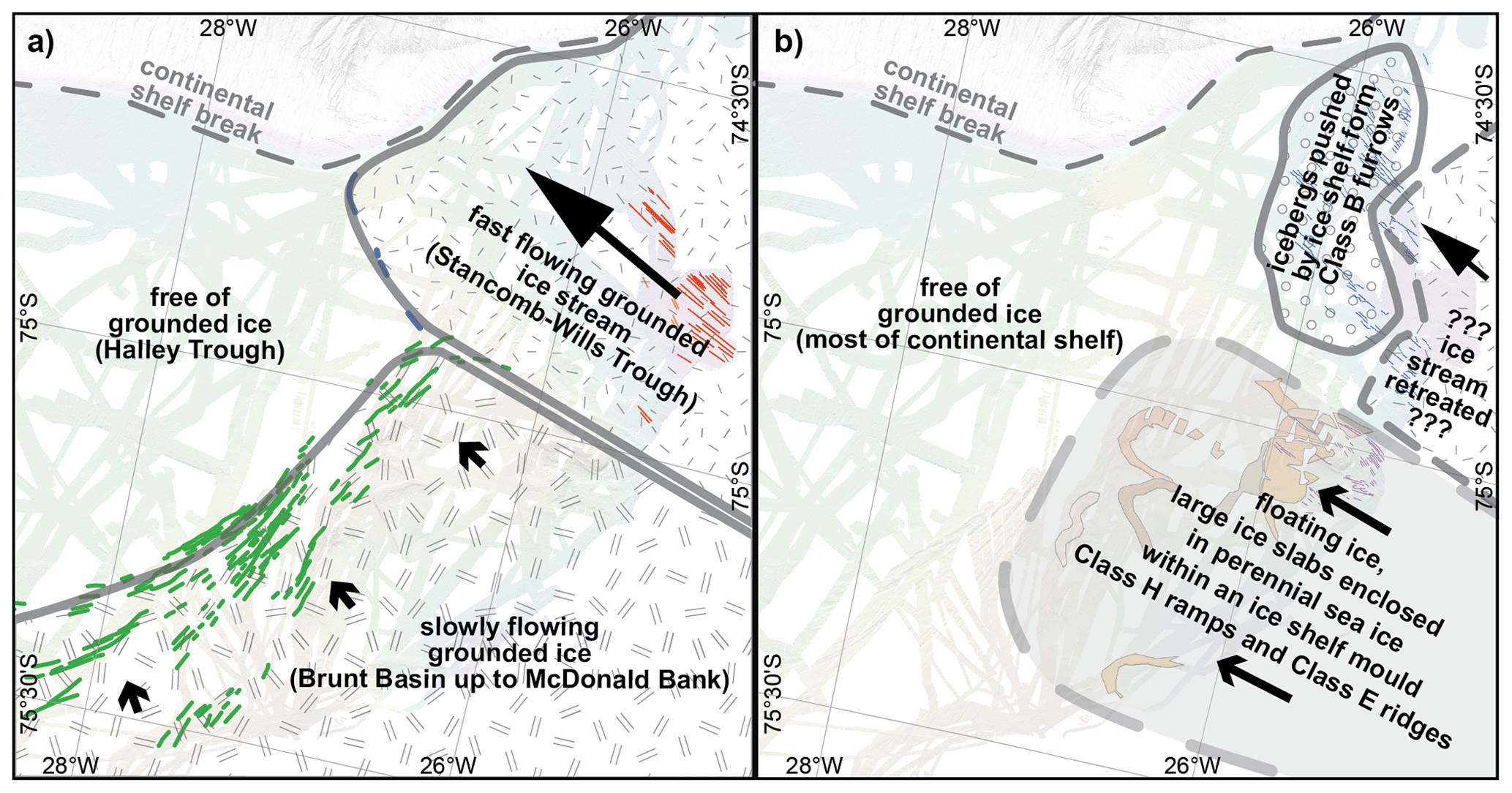
Figure 11Schematic illustrating the two reconstructed glaciological regimes in Brunt Basin and on McDonald Bank: (a) the first regime with slow-flowing grounded ice forming Class I ridges at its margin and (b) the second regime in which large ice slabs mould Class H ramps and Class E ridges. Background and landforms relevant for the respective regimes correspond to Fig. 2.
After grounding-line retreat landward of the southeasternmost GZW by 10.5 ka cal BP, icebergs with drafts reaching up to a modern-day water depth of 600 m calved from the front of the Stancomb-Wills paleo-ice-stream, as is documented by the maximum water depth of iceberg plough marks in the trough. Furthermore, the nearly parallel orientation of the innermost plough marks aligned with the trough's long axis shows that the iceberg trajectories were to some extent constrained. The icebergs were probably enclosed within sea ice, with the ice shelf motion pushing the icebergs further offshore.
The ice shelf itself was most probably pinned for some time on the easternmost and shallowest part of the ESE-pointing branch of the T crossbar of McDonald Bank (196 m minimum water depth), which at that time acted as an ice shelf pinning point similar to the bed beneath the McDonald Ice Rumples today. Hence, this shoal is even shallower than the McDonald Ice Rumples, which are less than 220 m deep (Hodgson et al., 2019). Therefore, an extended ice shelf, even with modern-day thickness, would be able to ground on the shoal and thus be buttressed by the ice grounded on this pinning point.
5.2.3 Glacial history of Brunt Basin and McDonald Bank
In contrast to Stancomb-Wills Trough, landforms indicative of fast-flowing ice, i.e. MSGLs, are lacking in Brunt Basin and on McDonald Bank. Hence, at least during the most recent glaciation, no paleo-ice-stream flowed through Brunt Basin. Instead, the formation of the Class H ramps by large tabular icebergs and of the Class I ridges and grooves by ice-marginal processes suggests that two other glaciological regimes affected this area during the past (Fig. 11). The first regime was characterized by a phase of slowly flowing, grounded ice covering Brunt Basin up to the western flank of McDonald Bank (Fig. 11a). Retreat of this slowly flowing, grounded ice from McDonald Bank was likely rapid, as further ice marginal landforms indicative of stepwise retreat, i.e. moraines, are absent on the eastern flank of the bank. However, processes active in the second regime may have reworked the seabed sediments, possibly including recessional moraines, subsequent to grounded ice retreat. This second glaciological regime was characterized by presence of floating ice within Brunt Basin. Thick, large ice slabs enclosed in perennial sea ice within an ice shelf, similar to the modern-day situation in the suture zone between Brunt Ice Shelf and Stancomb-Wills Glacier Tongue, moulded ramps into the eastern flank of McDonald Bank (Fig. 11b).
There are barely any chronological constraints for these two regimes, including their relative temporal order (see Sect. 5.2.1). Some grooves of Class I seem to incise into the western parts of ramps 1 and 3 (Fig. 3). This suggests that at least the formation of these two outer ramps predates the phase of slow grounded ice flow on McDonald Bank. However, according to our interpretation that individual thick icebergs formed the ramps, these events themselves likely occurred intermittently over an extended period of time. This may indicate that the formation of some ramps occurred before and the formation of other ramps occurred after the phase of slow grounded ice flow in Brunt Basin. Either way, the ramps show that the Brunt–Stancomb-Wills ice shelf system was repeatedly buttressed and, therefore, to some degree “stabilized” by McDonald Bank in a similar way to the modern Brunt Ice Shelf is now buttressed by the McDonald Ice Rumples. As a consequence of decreasing ice drainage through Stancomb-Wills Trough, the transport direction of icebergs enclosed in the suture zone shifted northwards and ice shelf extent may have decreased. At some point, these icebergs did not reach McDonald Bank anymore, leaving the modern McDonald Ice Rumples as the only pinning point for the ice shelf until today.
The absence of a lateral topographic constraint for the Stancomb-Wills paleo-ice-stream on the outer shelf as suggested by the lateral marginal moraine (Class F) is in line with the observation of slow, grounded ice flow on McDonald Bank as far north as the limit of the ridges and grooves (Class I) observed on its western flank. Thus, the geographic relation of these two landform classes suggests that their formation coincided. This also implies that the area offshore from the ridges and grooves, i.e. Halley Trough, was free of grounded ice during this phase of glaciation. Therefore, Halley Trough may represent a refuge, where benthic shelf communities on the Weddell Sea shelf survived the LGM in situ (Barnes and Hillenbrand, 2010).
The glacial morphology on the northeastern WSE shelf shows that in times of an extended EAIS most ice was discharged through Stancomb-Wills Trough, which probably extends about 200 km upstream of the modern-day grounding line. Retreat of grounded ice in the trough was stepwise, with at least three phases of grounding-line still-stands, during which GZWs were formed in the trough. Thereafter, an ice shelf was present in the trough, as documented by the almost parallel orientation of linear iceberg plough marks in the deep outer section of the trough.
In Brunt Basin and on McDonald Bank, the existence of two other glaciological regimes is inferred from the data. One regime was characterized by slowly flowing, grounded ice that covered Brunt Basin westward up to a set of ridges and grooves on the western edge of McDonald Bank. At the same time, grounded ice was absent in Halley Trough, suggesting that this trough may have been a refuge for benthic shelf fauna during the LGM. The other regime was characterized by the presence of floating ice within Brunt Basin. Large ice slabs enclosed and steered by perennial sea ice, similar to the modern-day situation within the suture zone between Brunt Ice Shelf and Stancomb-Wills Glacier Tongue, ran aground on the eastern side of McDonald Bank and were subsequently pushed seaward by ice shelf advance to mould ramps into the seafloor. Such ramps have not been observed elsewhere on formerly glaciated margins, probably because their formation requires a unique ice shelf setting as it is provided by the Brunt–Stancomb-Wills ice shelf system. The ramps imply that on several occasions in the past the Brunt–Stancomb-Wills ice shelf system was repeatedly buttressed and stabilized by icebergs pinned on McDonald Bank. After a northward shift of the iceberg trajectories, the modern McDonald Ice Rumples remained the only pinning point of the ice shelf until today.
The chronological constraints of ice sheet retreat in the study area remain sparse. Nevertheless, our data provide a new minimum age for grounded ice retreat from inner Stancomb-Wills Trough of 10.5 ka cal BP. For Brunt Basin, the question of whether the area was overrun by grounded ice during the LGM remains unresolved. Core 3-7-1 is open to alternative interpretations regarding this question due to down-core age reversals and, as shown here, the unclear geographical core location and thus unclear geomorphological context.
The compiled AWI–BAS bathymetric data are available via PANGAEA: https://doi.org/10.1594/PANGAEA.907173 (Arndt and Larter, 2019). Sub-bottom profiler data of expeditions PS82, PS96, and PS111 can be requested from AWI via PANGAEA: https://doi.org/10.1594/PANGAEA.837893 (Damaske and Kuhn, 2014), https://doi.org/10.1594/PANGAEA.860442 (Arndt and Kuhn, 2016), and https://doi.org/10.1594/PANGAEA.897301 (Arndt and Niessen, 2019). TOPAS sub-bottom profiler data are available from the UK Polar Data Centre on request. Full results of analyses on sediment cores GC634 to GC637 are available from Claus-Dieter Hillenbrand on request.
The supplement related to this article is available online at: https://doi.org/10.5194/tc-14-2115-2020-supplement.
JEA, RDL, and CDH developed the concept and led the writing of this paper. JEA was responsible for compilation of used bathymetric data sets. CDH, SHS, MF, JAS, and RDL were responsible for the recovery and investigation of the marine sediment cores, with SHS carrying out most of the laboratory analyses. LW carried out the MICADAS radiocarbon dating. JEA, RDL, CDH, SHS, MF, and JAS interpreted the geomorphological and core data. All authors contributed to the writing of the manuscript.
The authors declare that they have no conflict of interest.
We thank all captains, crews, and scientists supporting and enabling acquisition of the scientific data and samples used in this study. We thank Hilmar Gudmundsson for sharing preselected Landsat imagery of the study area with no or very little cloud cover. We thank the reviewers Chris D. Clark and Frank O. Nitsche for providing constructive comments on an earlier version of this paper. This study is part of the Alfred Wegener Institute Helmholtz Centre for Polar and Marine Research programme “Polar Regions and Coasts in the Changing Earth System (PACES II)” and the BAS programme “Polar Science for Planet Earth”.
Jan Erik Arndt has been supported by the Deutsche Forschungsgemeinschaft (grant no. AR 1087/1-1). Simon H. Sørli and Matthias Forwick thank Aker BP ASA for financial support.
The article processing charges for this open-access
publication were covered by a Research
Centre of the Helmholtz Association.
This paper was edited by Ginny Catania and reviewed by Frank Nitsche and Chris Clark.
Alley, R. B., Blankenship, D. D., Bentley, C. R., and Rooney, S. T.: Deformation of till beneath ice stream B, West Antarctica, Nature, 322, 57–59, https://doi.org/10.1038/322057a0, 1986.
Alley, R. B., Blankenship, D. D., Rooney, S. T., and Bentley, C. R.: Sedimentation beneath ice shelves – the view from ice stream B, Mar. Geol., 85, 101–120, https://doi.org/10.1016/0025-3227(89)90150-3, 1989.
Anderson, J. B. and Andrews, J. T.: Radiocarbon constraints on ice sheet advance and retreat in the Weddell Sea, Antarctica, Geology, 27, 179–182, https://doi.org/10.1130/0091-7613(1999)027<0179:RCOISA>2.3.CO;2, 1999.
Anderson, J. B., Kurtz, D. D., Domack, E. W., and Balshaw, K. M.: Glacial and Glacial Marine Sediments of the Antarctic Continental Shelf, J. Geol., 88, 399–414, https://doi.org/10.1086/628524, 1980.
Anderson, J. B., Davis, S. B., Domack, E., Kurtz, D. D., Balshaw, K. M., and Wright, R.: Marine Sediment Core Descriptions: IWSOE 68, 69, 70, Deep Freeze 79, Department of Geology, Rice University, Houston, USA, 1981.
Arndt, J. E.: Marine geomorphological record of Ice Sheet development in East Greenland since the Last Glacial Maximum, J. Quatern. Sci., 33, 853–864, https://doi.org/10.1002/jqs.3065, 2018.
Arndt, J. E. and Larter, R. D.: Swath Bathymetry compilation offshore Brunt Ice Shelf, PANGAEA, https://doi.org/10.1594/PANGAEA.907173, 2019.
Arndt, J. E. and Kuhn, G.: Profile of sediment echo sounding during POLARSTERN cruise PS96 (ANT-XXXI/2 FROSN) with links to ParaSound data files, Alfred Wegener Institute, Helmholtz Centre for Polar and Marine Research, Bremerhaven, PANGAEA, https://doi.org/10.1594/PANGAEA.860442, 2016.
Arndt, J. E. and Niessen, F.: Profile of sediment echo sounding during POLARSTERN cruise PS111 with links to ParaSound data files, Alfred Wegener Institute, Helmholtz Centre for Polar and Marine Research, Bremerhaven, PANGAEA, https://doi.org/10.1594/PANGAEA.897301, 2019.
Arndt, J. E., Schenke, H. W., Jakobsson, M., Nitsche, F. O., Buys, G., Goleby, B., Rebesco, M., Bohoyo, F., Hong, J.-K., Black, J., Greku, R., Udintsev, G., Barrios, F., Reynoso-Peralta, W., Taisei, M., and Wigley, R.: The International Bathymetric Chart of the Southern Ocean (IBCSO) Version 1.0 – A new bathymetric compilation covering circum-Antarctic waters, Geophys. Res. Lett., 40, 3111–3117, https://doi.org/10.1002/grl.50413, 2013.
Arndt, J. E., Hillenbrand, C.-D., Grobe, H., Kuhn, G., and Wacker, L.: Evidence for a dynamic grounding line in outer Filchner Trough, Antarctica, until the early Holocene, Geology, 45, 1035–1038, https://doi.org/10.1130/G39398.1, 2017.
Barnes, D. K. A. and Hillenbrand, C. D.: Faunal evidence for a late quaternary trans-Antarctic seaway, Glob. Change Biol., 16, 3297–3303, https://doi.org/10.1111/j.1365-2486.2010.02198.x, 2010.
Batchelor, C. L. and Dowdeswell, J. A.: Ice-sheet grounding-zone wedges (GZWs) on high-latitude continental margins, Mar. Geol., 363, 65–92, https://doi.org/10.1016/j.margeo.2015.02.001, 2015.
Batchelor, C. L. and Dowdeswell, J. A.: Lateral shear-moraines and lateral marginal-moraines of palaeo-ice streams, Quaternary Sci. Rev., 151, 1–26, https://doi.org/10.1016/j.quascirev.2016.08.020, 2016.
Bentley, M. J., Fogwill, C. J., Le Brocq, A. M., Hubbard, A. L., Sugden, D. E., Dunai, T. J., and Freeman, S. P. H. T.: Deglacial history of the West Antarctic Ice Sheet in the Weddell Sea embayment: Constraints on past ice volume change, Geology, 38, 411–414, https://doi.org/10.1130/g30754.1, 2010.
Bjarnadóttir, L. R., Ottesen, D., Dowdeswell, J. A., and Bugge, T.: Unusual iceberg ploughmarks on the Norwegian continental shelf, Geological Society, London, Memoirs, 46, 283–284, https://doi.org/10.1144/m46.126, 2016.
Caress, D. W. and Chayes, D. N.: Improved processing of Hydrosweep DS multibeam data on the R/V Maurice Ewing, Mar. Geophys. Res., 18, 631–650, https://doi.org/10.1007/bf00313878, 1996.
Caress, D. W., Chayes, D. N., and dos Santos Ferreira, C.: MBSystem: Mapping the Seafloor, available at: https://www.mbari.org/products/research-software/mb-system (last access: 16 June 2020), 2019.
Clark, C. D.: Mega-scale glacial lineations and cross-cutting ice-flow landforms, Earth Surf. Proc. Land., 18, 1–29, https://doi.org/10.1002/esp.3290180102, 1993.
Damaske, D. and Kuhn, G.: Profile of sediment echo sounding during POLARSTERN cruise PS82 (ANT-XXIX/9) with links to ParaSound data files, Alfred Wegener Institute, Helmholtz Centre for Polar and Marine Research, Bremerhaven, PANGAEA, https://doi.org/10.1594/PANGAEA.837893, 2014.
De Rydt, J., Gudmundsson, G. H., Nagler, T., Wuite, J., and King, E. C.: Recent rift formation and impact on the structural integrity of the Brunt Ice Shelf, East Antarctica, The Cryosphere, 12, 505–520, https://doi.org/10.5194/tc-12-505-2018, 2018.
Fretwell, P., Pritchard, H. D., Vaughan, D. G., Bamber, J. L., Barrand, N. E., Bell, R., Bianchi, C., Bingham, R. G., Blankenship, D. D., Casassa, G., Catania, G., Callens, D., Conway, H., Cook, A. J., Corr, H. F. J., Damaske, D., Damm, V., Ferraccioli, F., Forsberg, R., Fujita, S., Gim, Y., Gogineni, P., Griggs, J. A., Hindmarsh, R. C. A., Holmlund, P., Holt, J. W., Jacobel, R. W., Jenkins, A., Jokat, W., Jordan, T., King, E. C., Kohler, J., Krabill, W., Riger-Kusk, M., Langley, K. A., Leitchenkov, G., Leuschen, C., Luyendyk, B. P., Matsuoka, K., Mouginot, J., Nitsche, F. O., Nogi, Y., Nost, O. A., Popov, S. V., Rignot, E., Rippin, D. M., Rivera, A., Roberts, J., Ross, N., Siegert, M. J., Smith, A. M., Steinhage, D., Studinger, M., Sun, B., Tinto, B. K., Welch, B. C., Wilson, D., Young, D. A., Xiangbin, C., and Zirizzotti, A.: Bedmap2: improved ice bed, surface and thickness datasets for Antarctica, The Cryosphere, 7, 375–393, https://doi.org/10.5194/tc-7-375-2013, 2013.
Gales, J. A., Leat, P. T., Larter, R. D., Kuhn, G., Hillenbrand, C. D., Graham, A. G. C., Mitchell, N. C., Tate, A. J., Buys, G. B., and Jokat, W.: Large-scale submarine landslides, channel and gully systems on the southern Weddell Sea margin, Antarctica, Mar. Geol., 348, 73–87, https://doi.org/10.1016/j.margeo.2013.12.002, 2014.
Gales, J. A., Larter, R. D., and Leat, P. T.: Iceberg ploughmarks and associated sediment ridges on the southern Weddell Sea margin, Geol. Soc. Memoirs, 46, 289–290, https://doi.org/10.1144/m46.11, 2016.
Greenwood, S. L., Simkins, L. M., Halberstadt, A. R. W., Prothro, L. O., and Anderson, J. B.: Holocene reconfiguration and readvance of the East Antarctic Ice Sheet, Nat. Commun., 9, 3176, https://doi.org/10.1038/s41467-018-05625-3, 2018.
Gudmundsson, G. H., De Rydt, J. A. N., and Nagler, T.: Five decades of strong temporal variability in the flow of Brunt Ice Shelf, Antarctica, J. Glaciol., 63, 164–175, https://doi.org/10.1017/jog.2016.132, 2016.
Hein, A. S., Fogwill, C. J., Sugden, D. E., and Xu, S.: Glacial/interglacial ice-stream stability in the Weddell Sea embayment, Antarctica, Earth Planet. Sc. Lett., 307, 211–221, https://doi.org/10.1016/j.epsl.2011.04.037, 2011.
Hillenbrand, C.-D., Melles, M., Kuhn, G., and Larter, R. D.: Marine geological constraints for the grounding-line position of the Antarctic Ice Sheet on the southern Weddell Sea shelf at the Last Glacial Maximum, Quaternary Sci. Rev., 32, 25–47, https://doi.org/10.1016/j.quascirev.2011.11.017, 2012.
Hillenbrand, C.-D., Kuhn, G., Smith, J. A., Gohl, K., Graham, A. G. C., Larter, R. D., Klages, J. P., Downey, R., Moreton, S. G., Forwick, M., and Vaughan, D. G.: Grounding-line retreat of the West Antarctic Ice Sheet from inner Pine Island Bay, Geology, 41, 35–38, https://doi.org/10.1130/G33469.1, 2013.
Hillenbrand, C.-D., Bentley, M. J., Stolldorf, T. D., Hein, A. S., Kuhn, G., Graham, A. G. C., Fogwill, C. J., Kristoffersen, Y., Smith, J. A., Anderson, J. B., Larter, R. D., Melles, M., Hodgson, D. A., Mulvaney, R., and Sugden, D. E.: Reconstruction of changes in the Weddell Sea sector of the Antarctic Ice Sheet since the Last Glacial Maximum, Quaternary Sci. Rev., 100, 111–136, https://doi.org/10.1016/j.quascirev.2013.07.020, 2014.
Hodgson, D. A., Hogan, K., Smith, J. M., Smith, J. A., Hillenbrand, C.-D., Graham, A. G. C., Fretwell, P., Allen, C., Peck, V., Arndt, J.-E., Dorschel, B., Hübscher, C., Smith, A. M., and Larter, R.: Deglaciation and future stability of the Coats Land ice margin, Antarctica, The Cryosphere, 12, 2383–2399, https://doi.org/10.5194/tc-12-2383-2018, 2018.
Hodgson, D. A., Jordan, T. A., De Rydt, J., Fretwell, P. T., Seddon, S. A., Becker, D., Hogan, K. A., Smith, A. M., and Vaughan, D. G.: Past and future dynamics of the Brunt Ice Shelf from seabed bathymetry and ice shelf geometry, The Cryosphere, 13, 545–556, https://doi.org/10.5194/tc-13-545-2019, 2019.
Hulbe, C. L., Johnston, R., Joughin, I., and Scambos, T.: Marine Ice Modification of Fringing Ice Shelf Flow, 3, BIO ONE, 323–330, 328 pp., 2005.
Jakobsson, M., Anderson, J. B., Nitsche, F. O., Dowdeswell, J. A., Gyllencreutz, R., Kirchner, N., Mohammad, R., O'Regan, M., Alley, R. B., Anandakrishnan, S., Eriksson, B., Kirshner, A., Fernandez, R., Stolldorf, T., Minzoni, R., and Majewski, W.: Geological record of ice shelf break-up and grounding line retreat, Pine Island Bay, West Antarctica, Geology, 39, 691–694, https://doi.org/10.1130/G32153.1, 2011.
Jordan, T. A. and Becker, D.: Investigating the distribution of magmatism at the onset of Gondwana breakup with novel strapdown gravity and aeromagnetic data, Phys. Earth Planet. In., 282, 77-88, https://doi.org/10.1016/j.pepi.2018.07.007, 2018.
King, E. C., Hindmarsh, R. C. A., and Stokes, C. R.: Formation of mega-scale glacial lineations observed beneath a West Antarctic ice stream, Nat. Geosci., 2, 585–588, https://doi.org/10.1038/ngeo581, 2009.
King, E. C., De Rydt, J., and Gudmundsson, G. H.: The internal structure of the Brunt Ice Shelf from ice-penetrating radar analysis and implications for ice shelf fracture, The Cryosphere, 12, 3361–3372, https://doi.org/10.5194/tc-12-3361-2018, 2018.
Klages, J. P., Kuhn, G., Hillenbrand, C. D., Graham, A. G. C., Smith, J. A., Larter, R. D., and Gohl, K.: First geomorphological record and glacial history of an inter-ice stream ridge on the West Antarctic continental shelf, Quaternary Sci. Rev., 61, 47–61, https://doi.org/10.1016/j.quascirev.2012.11.007, 2013.
Klages, J. P., Kuhn, G., Graham, A. G. C., Hillenbrand, C. D., Smith, J. A., Nitsche, F. O., Larter, R. D., and Gohl, K.: Palaeo-ice stream pathways and retreat style in the easternmost Amundsen Sea Embayment, West Antarctica, revealed by combined multibeam bathymetric and seismic data, Geomorphology, 245, 207–222, https://doi.org/10.1016/j.geomorph.2015.05.020, 2015.
Larter, R. D., Graham, A. G. C., Hillenbrand, C.-D., Smith, J. A., and Gales, J. A.: Late Quaternary grounded ice extent in the Filchner Trough, Weddell Sea, Antarctica: new marine geophysical evidence, Quaternary Sci. Rev., 53, 111–122, https://doi.org/10.1016/j.quascirev.2012.08.006, 2012.
Larter, R. D., Hogan, K. A., Hillenbrand, C.-D., Smith, J. A., Batchelor, C. L., Cartigny, M., Tate, A. J., Kirkham, J. D., Roseby, Z. A., Kuhn, G., Graham, A. G. C., and Dowdeswell, J. A.: Subglacial hydrological control on flow of an Antarctic Peninsula palaeo-ice stream, The Cryosphere, 13, 1583–1596, https://doi.org/10.5194/tc-13-1583-2019, 2019.
Lawver, L., Lee, J., Kim, Y., and Davey, F.: Flat-topped mounds in western Ross Sea: Carbonate mounds or subglacial volcanic features?, Geosphere, 8, 645–653, https://doi.org/10.1130/ges00766.1, 2012.
Lewis, C. F. M., Todd, B. J., Sonnichsen, G. V., and King, T.: Iceberg–seabed interaction on northwestern Makkovik Bank, Labrador Shelf, Canada, Geol. Soc. Memoirs, 46, 279–280, https://doi.org/10.1144/m46.95, 2016.
Lien, R., Solheim, A., Elverhøi, A., and Rokoengen, K.: Iceberg scouring and sea bed morphology on the eastern Weddell Sea shelf, Antarctica, Polar Res., 7, 43–57, https://doi.org/10.1111/j.1751-8369.1989.tb00603.x, 1989.
Livingstone, S. J., Ó Cofaigh, C., Stokes, C. R., Hillenbrand, C.-D., Vieli, A., and Jamieson, S. S. R.: Antarctic palaeo-ice streams, Earth-Sci. Rev., 111, 90–128, https://doi.org/10.1016/j.earscirev.2011.10.003, 2012.
Mouginot, J., Rignot, E., Scheuchl, B., and Millan, R.: Comprehensive Annual Ice Sheet Velocity Mapping Using Landsat-8, Sentinel-1, and RADARSAT-2 Data, Remote Sensing, 9, 364, https://doi.org/10.3390/rs9040364, 2017.
Munsell Color (Firm): Munsell Soil Color Charts with Genuine Munsell Color Chips, Grand Rapids, MI, Munsell Color, 2010.
Nichols, K. A., Goehring, B. M., Balco, G., Johnson, J. S., Hein, A. S., and Todd, C.: New Last Glacial Maximum ice thickness constraints for the Weddell Sea Embayment, Antarctica, The Cryosphere, 13, 2935–2951, https://doi.org/10.5194/tc-13-2935-2019, 2019.
Ó Cofaigh, C., Dowdeswell, J. A., Allen, C. S., Hiemstra, J. F., Pudsey, C. J., Evans, J., and Evans, J. A. D.: Flow dynamics and till genesis associated with a marine-based Antarctic palaeo-ice stream, Quaternary Sci. Rev., 24, 709–740, https://doi.org/10.1016/j.quascirev.2004.10.006, 2005.
Ó Cofaigh, C., Dowdeswell, J. A., Evans, J., and Larter, R. D.: Geological constraints on Antarctic palaeo-ice-stream retreat, Earth Surf. Process. Land., 33, 513–525, https://doi.org/10.1002/esp.1669, 2008.
Ottesen, D. and Dowdeswell, J. A.: An inter–ice-stream glaciated margin: Submarine landforms and a geomorphic model based on marine-geophysical data from Svalbard, Geol. Soc. Am. Bull., 121, 1647–1665, https://doi.org/10.1130/b26467.1, 2009.
Piepenburg, D.: Seabed photographs taken along OFOS profiles during POLARSTERN cruise PS96 (ANT-XXXI/2 FROSN), PANGAEA, https://doi.org/10.1594/PANGAEA.862097, 2016.
Reimer, P. J., Bard, E., Bayliss, A., Beck, J. W., Blackwell, P. G., Ramsey, C. B., Buck, C. E., Cheng, H., Edwards, R. L., Friedrich, M., Grootes, P. M., Guilderson, T. P., Haflidason, H., Hajdas, I., Hatté, C., Heaton, T. J., Hoffmann, D. L., Hogg, A. G., Hughen, K. A., Kaiser, K. F., Kromer, B., Manning, S. W., Niu, M., Reimer, R. W., Richards, D. A., Scott, E. M., Southon, J. R., Staff, R. A., Turney, C. S. M., and van der Plicht, J.: IntCal13 and Marine13 Radiocarbon Age Calibration Curves 0–50,000 Years cal BP, Radiocarbon, 55, 1869–1887, https://doi.org/10.2458/azu_js_rc.55.16947, 2013.
Reinardy, B. T. I., Hiemstra, J. F., Murray, T., Hillenbrand, C.-D., and Larter, R. D.: Till genesis at the bed of an Antarctic Peninsula palaeo-ice stream as indicated by micromorphological analysis, Boreas, 40, 498–517, https://doi.org/10.1111/j.1502-3885.2010.00199.x, 2011.
Rise, L., Bellec, V. K., Ottesen, D., Bøe, R., and Thorsnes, T.: Hill–hole pairs on the Norwegian continental shelf, Geol. Soc. Memoirs, 46, 203–204, https://doi.org/10.1144/m46.42, 2016.
Stolldorf, T., Schenke, H.-W., and Anderson, J. B.: LGM ice sheet extent in the Weddell Sea: evidence for diachronous behavior of Antarctic Ice Sheets, Quaternary Sci. Rev., 48, 20–31, https://doi.org/10.1016/j.quascirev.2012.05.017, 2012.
Stuiver, M. and Reimer, P. J.: Extended 14C data-base and revised calib. 3.0 C-14 age calibration program, Radiocarbon, 35, 215–230, 1993.
Synal, H.-A., Stocker, M., and Suter, M.: MICADAS: A new compact radiocarbon AMS system, Nucl. Instrum. Meth. B, 259, 7–13, https://doi.org/10.1016/j.nimb.2007.01.138, 2007.
The RAISED Consortium: Bentley, M. J., Ó Cofaigh, C., Anderson, J. B., Conway, H., Davies, B., Graham, A. G. C., Hillenbrand, C.-D., Hodgson, D. A., Jamieson, S. S. R., Larter, R. D., Mackintosh, A., Smith, J. A., Verleyen, E., Ackert, R. P., Bart, P. J., Berg, S., Brunstein, D., Canals, M., Colhoun, E. A., Crosta, X., Dickens, W. A., Domack, E., Dowdeswell, J. A., Dunbar, R., Ehrmann, W., Evans, J., Favier, V., Fink, D., Fogwill, C. J., Glasser, N. F., Gohl, K., Golledge, N. R., Goodwin, I., Gore, D. B., Greenwood, S. L., Hall, B. L., Hall, K., Hedding, D. W., Hein, A. S., Hocking, E. P., Jakobsson, M., Johnson, J. S., Jomelli, V., Jones, R. S., Klages, J. P., Kristoffersen, Y., Kuhn, G., Leventer, A., Licht, K., Lilly, K., Lindow, J., Livingstone, S. J., Massé, G., McGlone, M. S., McKay, R. M., Melles, M., Miura, H., Mulvaney, R., Nel, W., Nitsche, F. O., O'Brien, P. E., Post, A. L., Roberts, S. J., Saunders, K. M., Selkirk, P. M., Simms, A. R., Spiegel, C., Stolldorf, T. D., Sugden, D. E., van der Putten, N., van Ommen, T., Verfaillie, D., Vyverman, W., Wagner, B., White, D. A., Witus, A. E., and Zwartz, D.: A community-based geological reconstruction of Antarctic Ice Sheet deglaciation since the Last Glacial Maximum, Quaternary Sci. Rev., 100, 1–9, https://doi.org/10.1016/j.quascirev.2014.06.025, 2014.
Thomas, R. H.: The dynamics of the Brunt Ice Shelf, Coats Land, Antarctica, British Antarctic Survey Scientific Reports, British Antarctic Survey, London, 79, 45 pp., 1973.
Wacker, L., Bonani, G., Friedrich, M., Hajdas, I., Kromer, B., Němec, M., Ruff, M., Suter, M., Synal, H. A., and Vockenhuber, C.: MICADAS: Routine and High-Precision Radiocarbon Dating, Radiocarbon, 52, 252–262, https://doi.org/10.1017/S0033822200045288, 2010.
Wise, M. G., Dowdeswell, J. A., Jakobsson, M., and Larter, R. D.: Evidence of marine ice-cliff instability in Pine Island Bay from iceberg-keel plough marks, Nature, 550, 506–510, https://doi.org/10.1038/nature24458, 2017.