the Creative Commons Attribution 4.0 License.
the Creative Commons Attribution 4.0 License.
 | 09 Mar 2023
Progress of the RADIX (Rapid Access Drilling and Ice eXtraction) fast-access drilling system
Jakob Schwander
Thomas F. Stocker
Remo Walther
Samuel Marending
RADIX (Rapid Access Drilling and Ice eXtraction) is a prospecting drilling system that has been designed, realized and tested on polar ice sheets. The goal of RADIX is to provide rapid, deep access for sampling of ice and downhole physical measurements that inform about ice sheet age and history and the integrity of layering. A 20 mm access hole is drilled with a hydraulic coiled tubing system where the tube consists of a plastic hose. The ice cuttings are flushed to the surface in normal circulation, i.e., between the hose and borehole wall, and can be sampled for analysis. After drilling, a dedicated logger with a 15 mm diameter is deployed into the hole for measuring the geometric orientation of the hole, the temperature profile and the dust content in the surrounding ice (optical dust logger). The equipment has been tested and improved during six field projects in Greenland and Antarctica. It is designed to ultimately drill through a 3000 m ice sheet within roughly 1 week. The greatest depth reached so far was 324 m during the last field project at Little Dome C.
- Article
(16205 KB) - Full-text XML
- BibTeX
- EndNote


In recent decades, ice core research has created an extensive knowledge base for climate history and glaciology. Yet in polar ice sheets there is the potential to extend that knowledge for example back in time (oldest ice projects) or with higher resolution for special time ranges or geographic areas (e.g., ice streams, West Antarctic Ice Sheet). Deep-ice-core-drilling projects are costly and time consuming. Fast-access ice drilling could be used to find suitable drilling sites in advance of new deep-core-drilling projects and therefore reduce costs and avoid drill sites with unfavorable conditions. Several fast-access drilling projects have been proposed and tested (Alemany et al., 2014; Clow and Koci, 2002; Goodge et al., 2021; Rix et al., 2019)
The University of Bern RADIX (Rapid Access Drilling and Ice eXtraction) project has been designed for drilling a very small-diameter hole with a depth range of up to 3 km. It aims at minimal overall resources and weight during field deployments. The concept of RADIX and first feasibility tests were published by Schwander et al. (2014). The present version of RADIX is still very close to this published concept, but many details have been improved or added based on a series of previous test drillings in Greenland, Antarctica and the laboratory. In the 2021/22 Antarctic season we drilled the so far deepest hole of 324 m at Little Dome C. Here we present the current status of the RADIX system and share our experiences and results from the fieldwork and from laboratory tests that were essential for the technical development of RADIX. Table 1 summarizes key parameters of the RADIX system.
Figure 1The RADIX system is housed in an inflatable, windproof shelter (dimensions: 7 m × 7 m × 5 m) from AXION (https://www.axion4event.com, last access: 27 February 2023).
2.1 Shelter
We use an inflatable 7 m × 7 m × 5 m white single-layer tent (AXION) as a drill shelter (Fig. 1). The tent has an inflatable tube in each corner (legs) and an inflatable frame of four tubes for stabilizing the upper part of the tent. Four side panels are zipped between the legs. The shelter is set up in a few hours, including securing for snow and wind. Two of the four side panels are equipped with zipper doors for access and temperature control. At average daily temperatures of −35 ∘C in Antarctica the tent provides a calm interior working space with temperatures close to the freezing point. One door is usually left open to prevent melting.
2.2 Firn drill
In order to set the casing and packer, a 40 mm diameter hole is drilled from the surface to the ice below the bubble close-off depth. The first 1.5 m is cut out with an aluminum pipe that is forced exactly vertically into the snow. Down to approximately 6 m we melt the hole with a heated copper device, which has a shape similar to a plumb bob (Fig. 2).

The upper part of the bob has a spherical bead. During melting, the bead hangs in the firn, allowing the melter to pivot to the vertical position by gravity, keeping the melting direction very close to vertical. While melting, it also glazes the hole wall, thus making it mechanically more stable and reducing the risk of snow falling into the hole. The remaining hole is then drilled with a dedicated electromechanical drill (Fig. 3). Two 40 W motors (26 mm diameter) and a planetary gear driving the 40 mm drill bit are housed in a stainless-steel pipe of 32 mm outer diameter connected to a 22 mm/19 mm (outer/inner diameter, henceforth), 120 m long vacuum pipe (polyamide tubing). The electrical power line is taped to the outside of the vacuum pipe. A 2 mm clearance between motors and the steel housing allows for the ice cuttings to pass from the drill bit to the vacuum pipe. At the entrance to the drill housing, behind the bit, a coffee-mill-like rotary cutter ensures that only small ice cuttings can enter the vacuum line. A Zephyr claw vacuum pump (C-VLR 60; 60 m3 h−1) provides enough flow for transporting the cuttings to the surface. A cyclonic separator between the vacuum line and pump collects the ice chips in a tank with a capacity for approximately 10 m drilling depth. The drill is lowered on the vacuum line and controlled by hand.
Figure 3A 40 mm firn drill on a vacuum line for lifting ice cuttings. All pieces were manufactured in the workshop of the Physics Institute, University of Bern.
2.3 Firn hole casing and packer
We use a 25 mm/21 mm HDPE (high-density polyethylene) water pipe for casing the firn hole. As the total weight of a 100 m casing is only about 14 kg it can be lowered or raised by hand. The casing is sealed to the solid ice at the bottom of the casing hole by means of a packer. The packer is made with a 0.7 m long rubber hose mounted on a stainless-steel tube (Fig. 4). The casing pipe is fed through the packer and screwed with thread sealant to an adapter mounted on the lower end of the steel tube. The rubber hose is inflated through a 3 mm/2 mm pneumatic hose taped to the outside of the casing. The low inherent physical stability of the thin-walled casing pipe causes the pipe to bend under its own weight. Therefore the pipe must be clamped to a lifting jack mounted on the drill tower and stretched in order to remove the bending in the hole. The packer is pressurized to approximately 3 bar above the hydrostatic pressure of the fluid at the level of the packer. The pressure is maintained by compressed air from a 7 L flask equipped with a pressure control valve. A manifold on the flask allows for refilling during operation by means of a breathing-air compressor. The casing extends about 1.3 m above the surface. During drilling the rising fluid exits through a side outlet tee at 1 m above the surface.
Figure 4Packer inserted into a Plexiglas tube to test inflation. The inner diameter of the tube is identical to the borehole diameter.
2.4 RADIX drill, anti-torque system and flow controller
Here we describe the RADIX drill components from the top to the bottom, in the direction of drilling. The drill (Fig. 5) is connected to a hydraulic hose with a rotary union. Below this adapter the drill is centered and stabilized against rotation by an anti-torque. The anti-torque is made with three vertical spring-loaded sharp skates with a rake angle on the cutting edge of −40∘. Below the anti-torque a pressure relief valve that can be set between 30 and 70 bar maintains a constant pressure while drilling and insures fluid flow into the hole even in the case of a blocked hydraulic motor. This is important to clear the hole from ice chips.
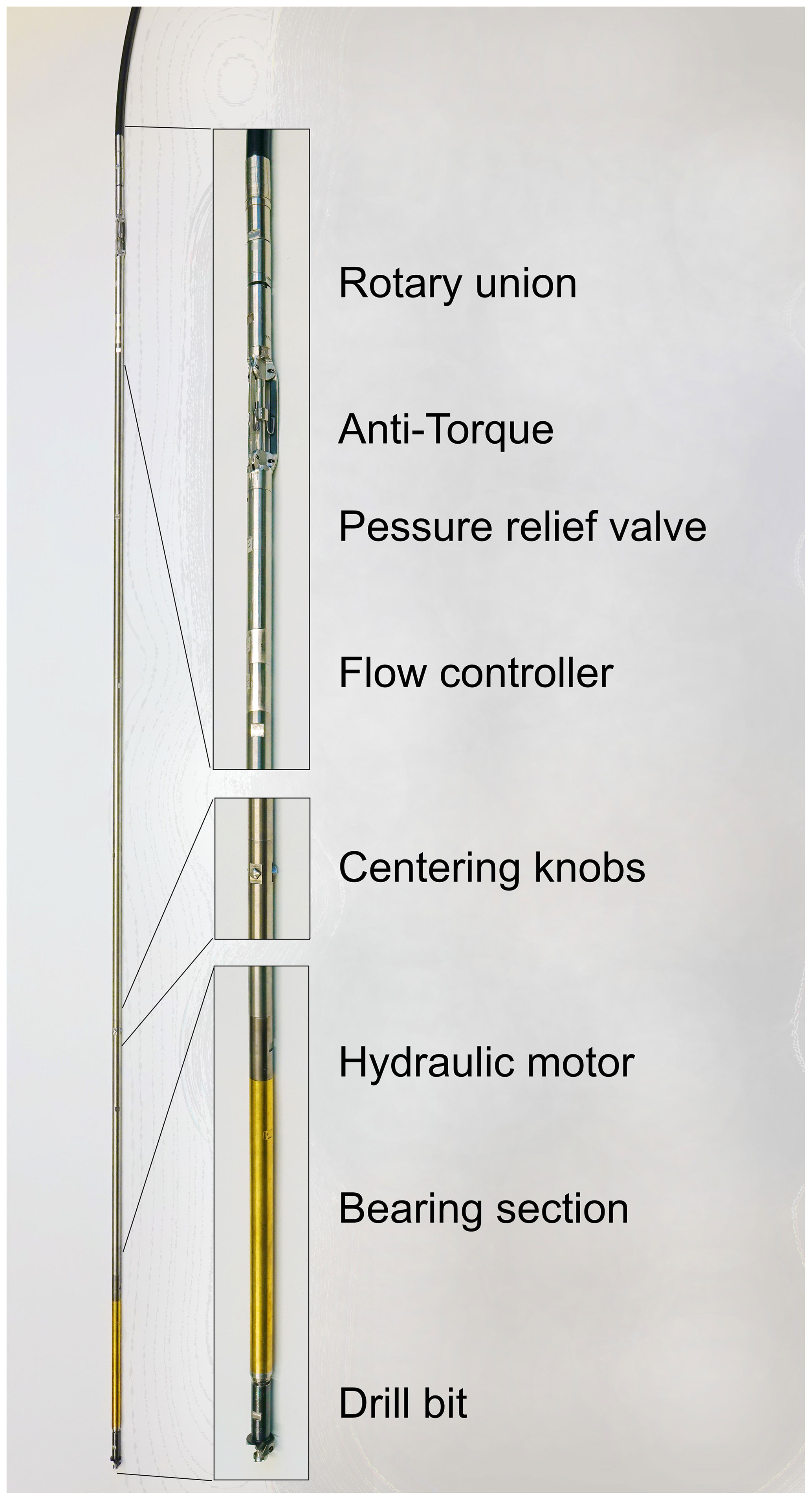
Figure 5RADIX fluid drill with tungsten extension tubes connected to the hydraulic hose (top).
The next component is a mechanical flow controller that provides an even flow and therefore a controlled rotation speed of the hydraulic motor. The operation principle of the flow controller is a fluid jet deflected on a spring-loaded pin (Fig. 6). The momentum change caused by the deflection moves the pin toward the spring and controls the flow by closing side channels in the pin housing.
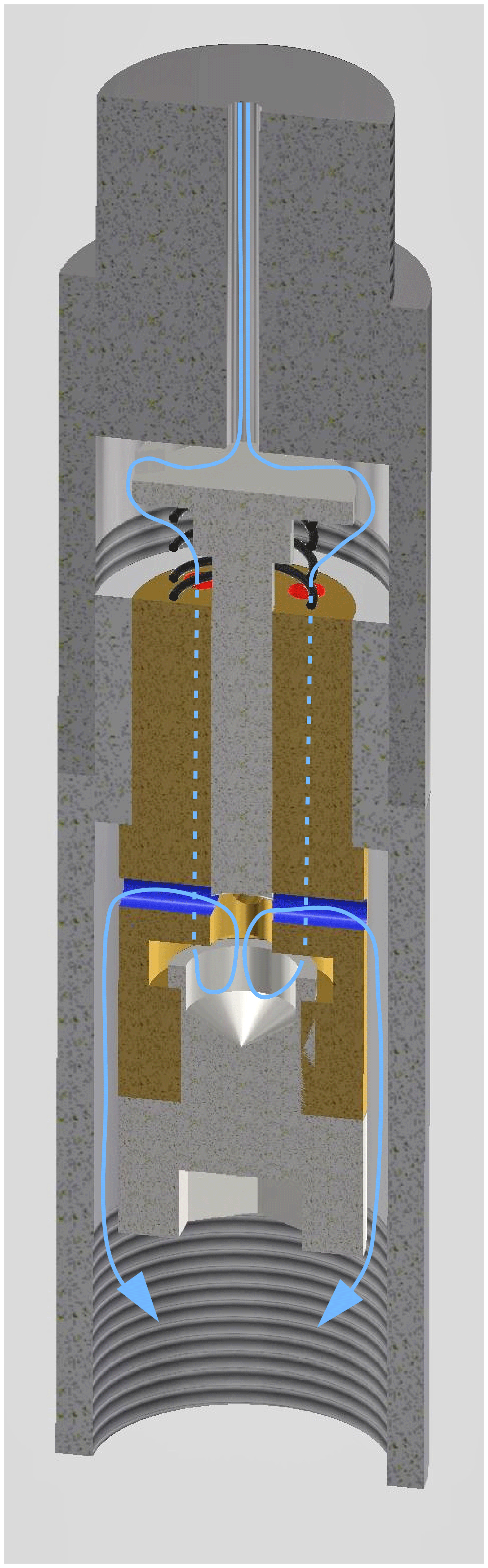
Figure 6Cross section through the mechanical flow controller. The direction of flow is from top to bottom. The fluid flows through the red holes below the deflection disk into the space below the pin and exits through the blue radial holes.
Between the flow controller and the hydraulic motor we have inserted six sections of 15 mm/5 mm tungsten tube with a total length of 1.58 m. These extensions add weight and reduce the tilt of the drill relative to the hole axis. Three centering knobs, which extend exactly to the diameter of the hole, are mounted on one of the tungsten sections. Besides reducing the overall bending of the drill, they let the lower end of the drill hang downward. Having these knobs at a well-determined position, they provide an auto-correction to verticality for an inclined hole.
The hydraulic motor is a five-/six-lobe Moineau motor (mud motor with five rotor lobes and six stator lobes) with a volume displacement of 2.96 cm3 per revolution. The nominal rotation speed is 10 to 15 rps (rotations per second), corresponding to a fluid flow rate of 30 to 45 cm3 s−1. Due to the leak flow between the rotor and stator, the effective flow rate through the motor is up to 50 % higher. The exact rotation speed depends on the drilling torque (about 1 N m) and the leak flow, which varies with the fluid viscosity and thus with temperature. The setting of the pressure relief valve has also some influence on the flow rate and therefore on the rotation speed.
The development and manufacturing of the hydraulic motor and the drill head represented the greatest challenges in the development of RADIX. They went through many development steps and have now reached a quality that allows for long run times and works well in the entire polar temperature range. Both the stator and rotor of the motor are made of maraging steel. Raw parts are laser-sintered on a 3-D printer. The stator hole is then formed by spark erosion, the rotor is micromachined on a computer numerical control (CNC) milling machine, both with an accuracy of mm. The rotor and stator are then polished against each other with an 800-grit boron carbide paste. After providing the connection threads, the parts are hardened and nitrated. Finally the parts are polished again against each other with a 3 µm diamond suspension.
Since the rotor movement of the Moineau motor is eccentric, its torque is transmitted to a concentric axis via a flexible shaft.
The drill bit has a hollow shaft so that the drilling fluid exits at the very tip of the bit. The bit consists of a two-stage drill (Fig. 7). The front center bit has a diameter of 10 mm and has two step-cutting edges. On the outside, the center bit further cuts a thread with a 0.75 mm pitch, which determines the penetration rate of the drill. The raw center bit is 3-D-printed in maraging steel. The thread is then micromachined on a CNC milling machine. The center bit is mounted into a 20 mm modified Forstner bit that widens the hole from 10 to 20 mm with two step-cutting edges.
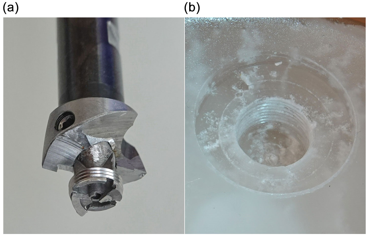
Figure 7RADIX 20 mm Forstner drill bit with an inserted 10 mm thread-cutting center bit (a). Test drilling in paraffin wax (b).
2.5 Coiled tubing system
The 13.6 mm/8 mm hydraulic hose is 3100 m long (aramid-reinforced Hytrel 5556, from Kutting UK). From the drill hole it passes over a 2 m circumference sheave mounted on a 2 m tower and is then coiled on a motor-driven drum with a rotary union for the inlet of the fluid. The sheave support is mounted on a bearing that allows for horizontal swiveling about the axis of the casing pipe. This pivoting lets the hose follow the coiling on the drum without the need for a special level wind system. The feed of the hose is measured by an electronic encoder on the sheave. The specific weight of the hose is slightly higher than that of the drilling fluid, providing a free-fall sinking velocity of about 0.15 m s−1. The maximum coiling velocity of the drum is about 0.6 m s−1, which is of course only applicable when pulling up. A load pin in the bearing of the sheave measures the drag on the hose. The winch motor is controlled manually or automatically. In automatic-drilling mode, the signal of the load pin is looped to the winch drive and controls feed of the hose. In this mode, the pull generated by the drill on the hose is kept at a preset value.
2.6 Fluid system and chip separation
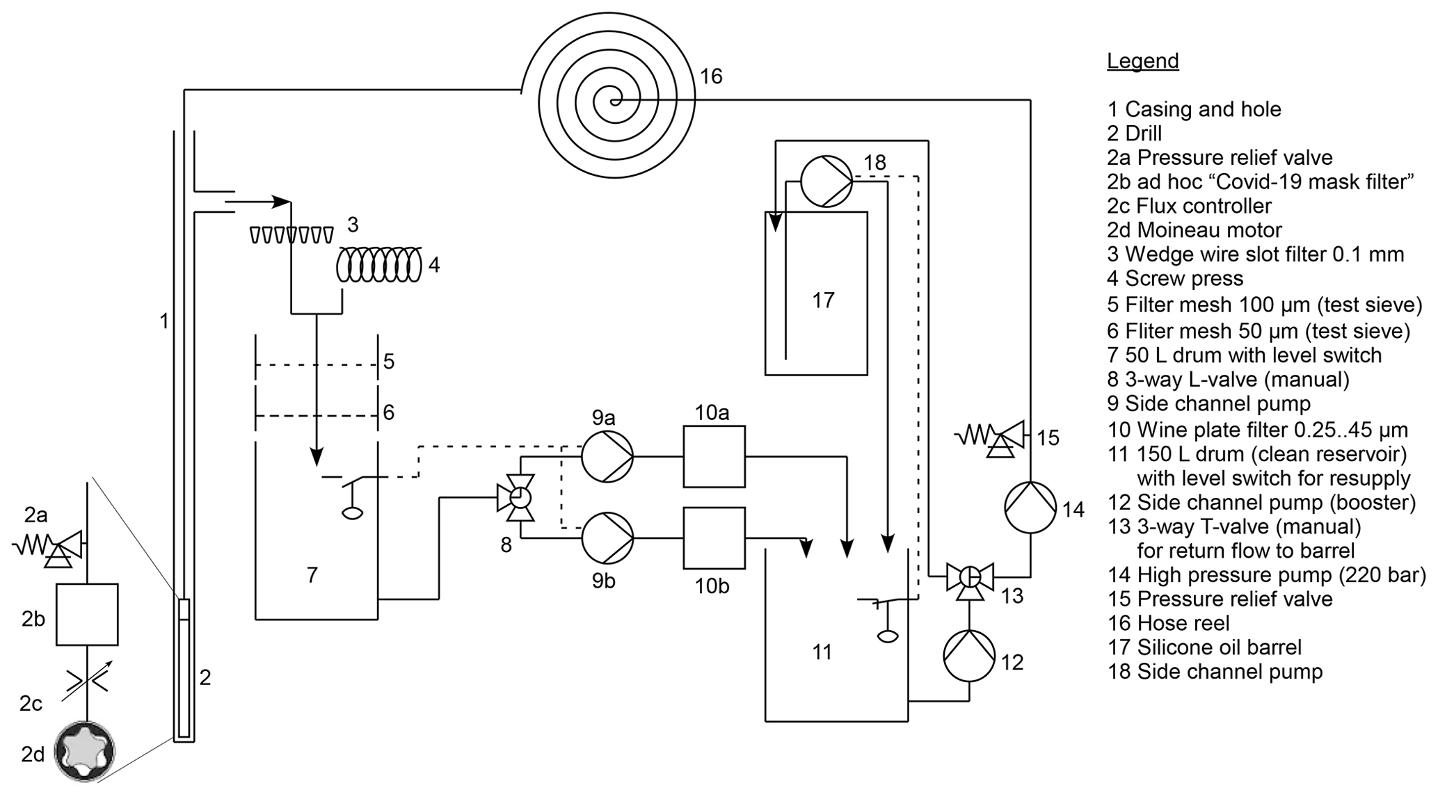
We use 1.5 cSt silicone oil (MD2M polysiloxane) as the drilling fluid. Its average in situ density matches the average in situ ice density at Dome Concordia very closely. Silicone oil from standard barrels is transferred by a level-switch-controlled pump to a 150 L drum (clean reservoir) (Figs. 8 and 10). From there a booster pump feeds the fluid to the 220 bar high-pressure triplex piston pump. A safety pressure relief valve at the outlet protects pump and downstream components. The high-pressure pump is connected to the rotary union of the hose drum. After passing through the hydraulic hose and the drill, the fluid carries the ice chips to the surface. The chip-loaded fluid exits through the side outlet tee near the top of the casing and flows onto a slotted wedge wire screen (Fig. 9). The screen is mounted on an adjustable vibrator, which also effects the forward movement of the slurry into the screw press where the separated chips are further dried.
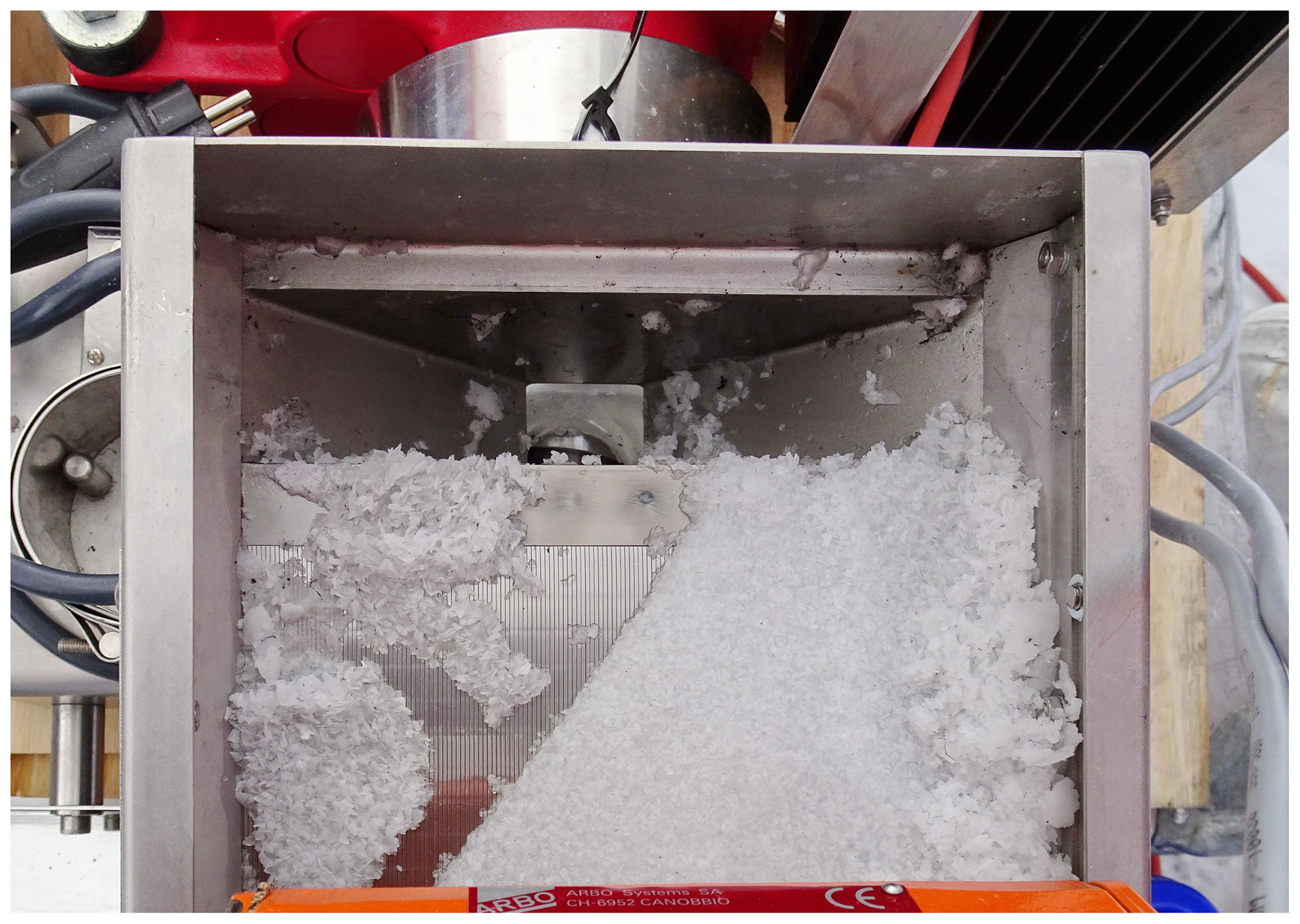
Figure 9Top view of fluid–chip separation on a slotted wedge wire screen. The slurry is moving upwards on the vibrating screen and falls into the screw press below.
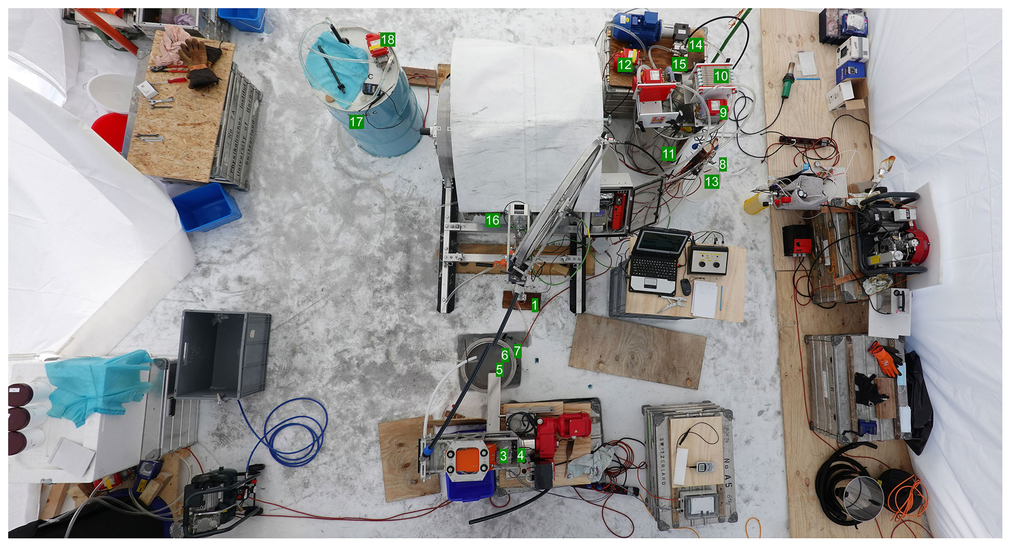
Figure 10Bird's-eye view of the RADIX system. Component numbers correspond to the legend in Fig. 8.
The fluid from the slotted screen and the screw press then passes a 100 and a 50 µm test sieve placed on a 50 L drum. The sieves are regularly swapped and cleaned. From the drum the fluid is transferred by a level-switch-controlled pump to a fine-fluid filter (wine plate filter 0.25 to 45 µm) from where the clean fluid drips into the 150 L drum and thus closes the fluid cycle. The ice chips from the test sieves and the ice pellets from the screw press are melted in a 200 L heated drum where water and silicone oil separate. The oil is transferred back to the fluid system after passing the test sieves and fine filter (Figs. 8 and 10).
2.7 Ice sampling
Instead of melting the ice pellets from the screw press they can be sampled from specific depths for further analysis. The pellets contain about 20 % of fluid. From deeper levels ascending chips will surface with a considerable delay. In addition they will be mixed from a broad depth range. The average time delay can be estimated with good accuracy from the fluid flow rate. The spread can be estimated for example by monitoring the decrease in chips in the fluid after stopping penetration but maintaining the flow of fluid. In order to sample from a specific depth, one would need to clear the hole from chips, then drill the requested depth interval and then flush all cuttings to the surface. Of course this is very time consuming and might be done for example only once close to bedrock.
2.8 Fluid recovery
A rubber sealing unit, similar to a small packer, can be mounted at the end of the previously emptied hydraulic hose for removing fluid from the hole. The hose with a sealing unit is lowered into the fluid-filled hole as deep as it sinks by its own weight. Then compressed air is blown through the hydraulic hose, which finally exits below the sealing unit. A pressure relief valve in the unit maintains a slight overpressure in the rubber sleeve, which consequently creates a seal to the hole wall. When the compressed air reaches the hydrostatic pressure at the level of the sealing unit, the hose is slowly lifted together with the fluid column above. The lifted fluid can then be collected through the tee outlet at the top of the casing. Several recovery cycles are needed to empty a deep hole.
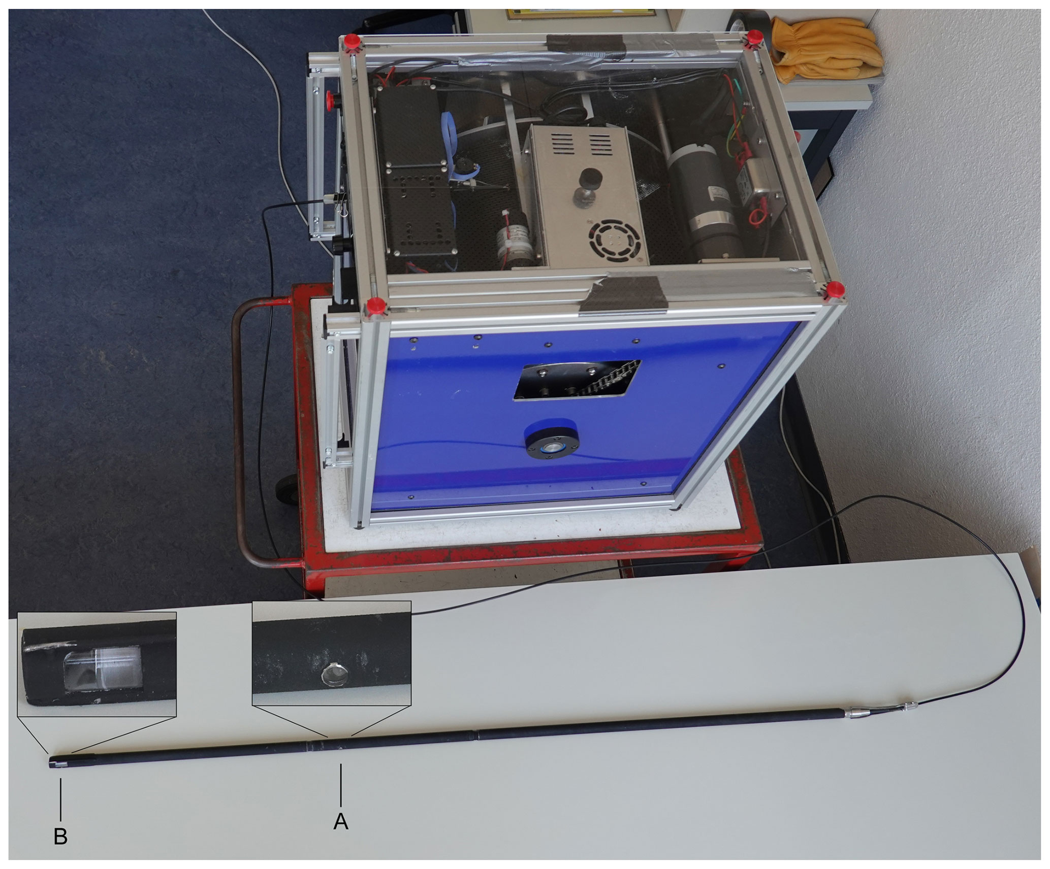
Figure 11Logger and 3.5 mm fiber-optic cable winch: A marks the emitting 405 nm LED; B marks the receiving window and mirror.
2.9 Bore hole logger
The RADIX logger is essentially independent of the drilling. It is deployed into the fluid-filled hole with its own winch and cable (Fig. 11). However, we use the same tower, sheave and depth counter as for drilling. A software adjustment is made in the depth counter to account for the smaller diameter of the cable. The logger is battery powered (eight AAA lithium batteries). The logging data are transmitted in real time over a single-mode fiber-optic Kevlar-reinforced HDPE cable with 3.5 mm outer diameter. The logging electronics are housed in a 15 mm/12 mm stainless-steel tube. The high-pressure seals are designed to withstand at least 300 bar.
The logger monitors temperature, 3-D acceleration, 3-D magnetic field, dust in the surrounding ice, and system voltages and currents. Data are measured and transmitted at a rate of approximately 10 s−1. They are stored in a database on a notebook computer together with the measured values of the depth counter. The data of the database are displayed in real time on the computer screen. Typically, we logged in dynamic mode at a velocity of 0.1 m s−1, yielding a depth resolution of 1 cm. However, the resolution of the dust recording is lower, as shown below.
The principle of the dust logger is based on the optical dust logger developed by Bay et al. (2001). Here we transmit blue light with a 2.4 W LED (405 nm) into the ice and measure the light scattered back by the dust particles in the ice with a 10 mm photomultiplier tube (Hamamatsu R1635). The light is transmitted and received through dedicated sapphire windows and a mirror soldered into the pressure housing. Both windows point to the same side of the logger and are separated by 0.38 m. The outside of the housing of the logger is painted with a black coating to minimize light traveling from the LED to the photomultiplier tube in the 2.5 mm gap between the hole wall and logger case. The sensitivity of the photomultiplier reaches down to single photons. In order to cover the expected range of backscattered light, the output power of the LED as well as the high voltage of the photomultiplier is cyclically switched between two values. While the LED power is switched every 0.1 s, the photomultiplier voltage changes only every 5 s because it needs a longer settling time. So a total of four sensitivity ranges are alternatively available within 10 s. The total sensitivity range is approximately −49 to −111 dB.
The backscattering of light from dust has been simulated numerically at CSEM (Centre Suisse d'Electronique et de Microtechnique) assuming a virtual ice block of m3 loaded with 2 × 10³ to 1 × 10⁶ dust particles per cubic centimeter. The particles have a diameter of 2 µm and cover approximately the range of the total geometrical cross section of the dust load observed in the European Project for Ice Coring in Antarctica (EPICA) Dome C ice core. The diameter of 2 µm corresponds to the mode of the measured dust particle size distribution (Potenza et al., 2016). The influence of the real size distribution compared to the assumed single size particles has not been investigated. The simulated average path length of the received scattered light is on the order of 0.5 m, meaning that the model geometry was sufficient. The expected range of backscattered light for the given detector geometry is −60 to −83 dB, which is very well within the specifications of the logger. Possible undesired light propagation between the logger and the borehole wall has also been simulated and is estimated to be several orders of magnitude below the reflected light from dust in the ice.
2.10 Electric power
By avoiding the heavy consumers (breathing-air compressor, triplex pump, heat gun) to run in parallel, a 230 V AC single-phase, 4 kW power source is sufficient to run RADIX. At Little Dome C we were in the comfortable situation of using power from the camp generator.
Erecting the shelter and installing the workplace for firn drilling is done in 1 work day. The net drilling time for a 110 m firn hole is approximately 10 h. However, especially in the first 30 m clogging of the drill by ice chips occurs frequently. The reason is that at shallow depths the drill may sink too quickly and the vacuum line gets too much ice at once. This requires lifting of the vacuum tube and drill, and in the simplest case, the blockage can be removed by tapping it out with a rubber hammer. But often the drill must be heated and dried. So 2 work days are typically required for the firn hole. The hole is then logged to check its inclination.
Next, the packer is screwed to the casing using a thread sealant, and the pneumatic hose for inflating the packer is attached and taped to the casing. The packer is inserted into a Plexiglas test pipe with the inner diameter equal to the one of the firn hole. After leak testing of the packer and the threaded connection to the casing with pressurized air, the casing is lowered into the firn hole. Beforehand a tiny amount of silicone grease is applied on the rubber packer because clean rubber tends to stick strongly on the ice and it can be difficult to loosen the packer at the end of drilling. During lowering, the casing is connected to the vacuum pump in order to remove falling snow from the hole so that the packer can be placed in an absolutely clean hole. The packer is set a few meters above the bottom and inflated to about 3 bar above the hydrostatic ice pressure.
Pressurized air is also applied to the casing to check that no porous firn layers are present in the last few meters of the hole. In the case of a negative test, the hole needs to be deepened. If the test has been favorable, the casing is lowered to the bottom of the hole, where the leak test is repeated. If the system is tight, the casing is cut to the correct length, stretched and filled with fluid. After temperature equilibration the fluid level should stay within a few centimeters for 24 h.
Installing the fluid system for the RADIX drill and setting up the winch with the hydraulic hose requires another work day.
As the body of the drill has a smaller diameter as the casing and as there might be a small gap below the casing, there is some risk that the drill bit could start a hole that is out of alignment with the casing. In order to avoid such offset, a square nut with a 20 mm outer diameter is mounted about 5 cm behind the drill bit. The nut guides the drill into a well-aligned starting hole. The nut can be removed after a successful start of drilling.
From now on, the drill could ideally be left in the hole for continuous drilling, preferably in auto-feed mode. The drill would need to be pulled up only for occasional logging of the hole. Even an overnight stoppage without removing the chips from the hole should be no problem. Ice cuttings in the hole seem to move easily after an interruption. However, at the present state, clogging or anti-torque rotation occurred frequently, requiring lifting the drill to the surface for maintenance. Reasons and suggested solutions are discussed below.
If the drill is pulled up, a small flow through the hose is maintained in order to lift the remaining ice chips to the surface. When lowering the drill back into the hole after maintenance, it is important to keep the pump running because the increasing pressure on the way down might otherwise press some fluid through the drill motor into the hose and force reverse rotation. The fluid in the hole still contains a certain amount of fine ice particles, which might get caught in the motor and block it. While drilling in a continuous mode, either manually or using the auto-feed, the majority of the work arises in connection with the maintenance of the fluid–chip separation system.
A substantial number of fine chips pass the slotted screen, which are collected in the 50 and 100 µm test sieves. They are changed and cleaned manually at intervals of a few minutes. The collected chips as well as the pellets from the screw press are manually transferred to the heated barrel for melting, from where the meltwater is discarded via a bottom faucet. The silicone fluid floating on top of the meltwater is recycled by pumping it back to the barrel, passing the test sieves and fine filter.
The RADIX system has been gradually improved during six campaigns in Greenland (Renland and EastGRIP) and Antarctica (Little Dome C) at the respective European deep-drilling sites.
4.1 Renland, 2015
A reduced system was tested on Renland ice cap in East Greenland. The drill hose was operated manually without a winch. A firn hole from the Danish RECAP project could be used. We attempted to connect the casing at the bottom of the firn hole by freezing it in a small volume of melted ice. A heat cartridge and a camera for monitoring the melting were lowered through the casing. When the lowest 0.1 m of the casing was resting in meltwater, the heat cartridge was removed and the water was left to refreeze. The casing was tightly connected to the ice and was filled with fluid. However, drilling through the end of the casing was difficult because the casing had been deformed by refreezing of the meltwater. Finally the casing was punched by the drill and was no longer tight. A different method to seal the casing was required.
4.2 EastGRIP, 2016
We used a first version of the hose winch with 500 m of hydraulic hose. We added a few brass extension tubes to the drill to increase the weight for better penetration. Melting of the ice at the bottom of the firn hole was done with a dedicated aluminum end tube with integrated heating elements attached to the PE casing. Melting and setting the casing was quick, but a substantial fluid leak was observed. This leak was caused by the decrease in volume of the ice during cooling, which resulted in a small gap between the aluminum tube and ice. In order to avoid this gap, we coated the tube with a 2 mm layer of silicone compound before the melting procedure. A small leak remained after melting and refreezing but immediately disappeared after filling the casing with fluid due to the swelling of the silicone compound by its contact with silicone oil. We were able to drill about 20 m below the casing.
Despite the additional weight of the extension tubes, we still had to slightly push on the hydraulic hose to invoke penetration of the drill. This was probably due to the friction of the twisted hose in the borehole. We suspected that sliding of the anti-torque skates caused twisting of the hose because no rotary union was installed between the drill and the hydraulic hose. The high-pressure triplex pump provided too low volume flux because of cavitation at the high altitude of the EastGRIP site. Separation of fluid and chips was done solely with the screw separator, which was quickly overloaded during continuous drilling.
4.3 EastGRIP, 2017
For the first time we drilled the firn hole with the dedicated mechanical firn drill. The difference to the present version was a smaller, 18 mm/15 mm vacuum pipe, and we used a small roots-type supercharger as a vacuum pump. Especially the smaller-diameter vacuum pipe turned out to provide a too small airflow, causing frequent clogging. We changed from a melt connection of the casing to a packer solution. We added the slotted-screen vibrator as a first separation step in the fluid circuit. The drill was equipped with a rotary union, and the drill bit had a thread-cutting specially ground center bit. We have installed a booster pump before the high-pressure pump to avoid cavitation.
For the first time we had a system that seemed to be apt for productive drilling. Unfortunately drilling was stopped early due to an internal air leak in the packer.
4.4 EastGRIP, 2018
The RADIX system was housed in the AXION tent for the first time as the drilling location was at the margin of the Northeast Greenland Ice Stream, about 30 km east of the EastGRIP camp. A 70 m firn hole was drilled with the electromechanical firn drill connected to a new claw vacuum pump and a 22 mm/19 mm vacuum pipe. The firn drilling was completed in 5 h. When attempting to drill in the fluid-filled hole with the RADIX drill, we encountered problems with PE cuttings from the casing. PE cuttings were produced by the up-and-down movement in the casing and by the rotating drill bit near the bottom of the casing. By applying a chamfer to the outer edge of the drill bit, the formation of PE shreds was largely prevented so that we finally succeeded to drill into the ice and, for the first time we could drill in auto-feed mode for about 10 m.
At 115 m depth the torque of the motor was not sufficient to drill further. The maximum torque was also partly limited by the relatively high leak flow through the motor. Improvement by a higher flow rate of the high-pressure pump was not possible by the limited volume flux of the booster pump.
First tests with the new logger were carried out. Transmission of the signal was not very stable, and the current of the special low-temperature batteries was too low. But we obtained first results on the inclination of the hole. Inclination reached up to 20∘ and increased especially where penetration was difficult. We interpreted the increasing inclination as a lack of traction on the drill head, assuming that we could maintain a vertical hole by holding the hose back and thus keep the drill in an upright position.
4.5 Little Dome C, 2019/2020
In preparation for this Antarctic drilling, we mainly worked on improving the torque of the hydraulic motor. We tried several coatings of the rotor and stator but finally found that hardening and nitrating was best suited for our purpose. A substantial improvement was achieved by replacing the previously used Al rod to transmit the rotation from the rotor to the bearing of the drill bit with a flexible shaft and the use of ball bearings instead of slide bearings. Fluid leakage between the rotor and stator was substantially reduced by new manufacturing processes. Instead of directly grinding 3-D selective-laser-sintered (SLS) stators and rotors, the SLS parts were used as raw bodies for the final machining by micromilling (rotor) and spark erosion (stator). We also installed a more powerful booster pump. Various improvements in the fluid–chip separation, e.g., a larger slotted screen, were also implemented.
Firn drilling to 107 m depth and setting the casing was done in 5 work days. No refilling of the 7 L compressed air bottle connected to the packer of the casing was needed throughout the whole drilling season.
The start of fluid drilling was difficult because of remains of frozen water in the new hydraulic hose. Normal operation was only possible after heating and flushing the hose with new silicone oil. Most of the drilling was then done in auto-feed mode. However, the deeper we got, the more the drill needed manual pushing down from the surface. At several occasions the drill got stuck and could only be freed after several hours of pulling with about 500 N on the hydraulic hose. Obviously the static pulling force on the thread-cutting center bit was much higher than the dynamic pulling. With increasing depth the motor torque became marginal again. We think this was due to a different cutting regime under high hydrostatic pressures (Yoshino, 2016). At a depth of 246 m we observed a slight uplift of the hydraulic hose when the fluid circulation was started, which we interpreted as a symptom of high inclination, and we decided to log the hole.
The unstable performance of the logger observed at EastGRIP had been corrected and a new type of Li battery with higher current rating was used (Energizer Ultimate Lithium L92 AAA). Indeed the inclination reached > 45∘ at 240 m depth, and thus, it turned out that holding the hose back to produce a negative load on the bit was not sufficient to maintain a vertical hole. The accuracy of the hole azimuth was restricted as the magnetic sensor showed a very high change in offset with temperature.
4.6 Little Dome C, 2021/22
With the cancellation of the 2020/21 Antarctic season due to the Covid-19 pandemic, a longer preparation period could be used to develop a number of improvements to RADIX to overcome the problems encountered in the first Antarctic drilling. A 50 % increase in torque of the hydraulic motor has been achieved by changing the geometry from three/four lobes to five/six lobes and by redesigning the pressure relieve valve on the drill for a maximum of 70 bar.
In the fluid system we have added plate filters to reduce the amount of small ice particles and added a heated barrel to improve the recycling efficiency of the fluid.
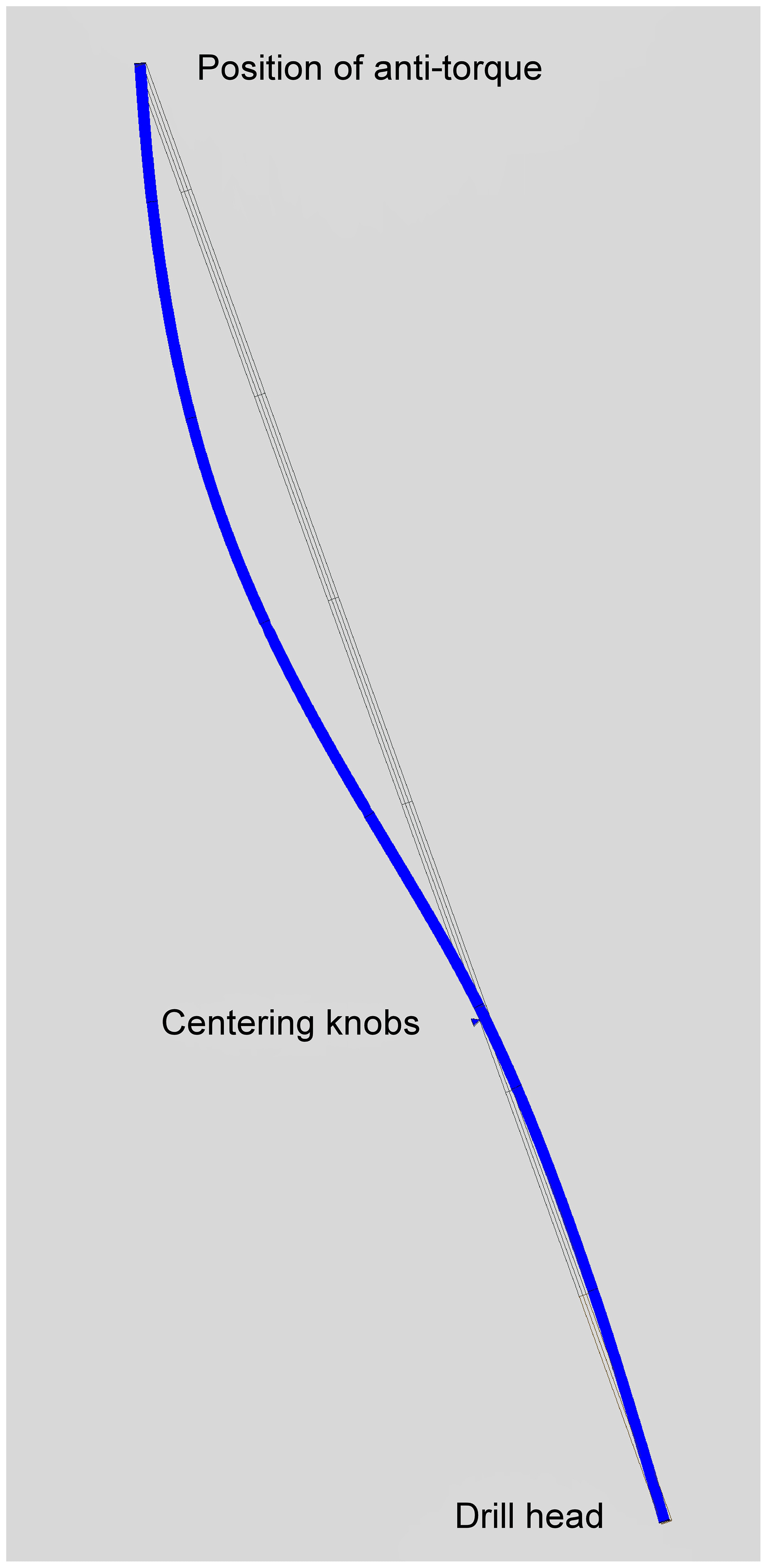
Figure 12Bending of drill by gravity (exaggerated). Finite-element simulation with actual material properties and tests with the drill itself led to an optimal position of the centering knobs at about one-third from the lower end.
To avoid a rapid increase in hole inclination as in the 2019/20 season, we implemented three major improvements: (i) a higher traction of the drill bit resulting from a substantially modified design (Fig. 7), (ii) increasing the weight and decreasing the bending of the drill by replacing brass with tungsten and (iii) a self-stabilization of the verticality by precisely positioning centering knobs. In an inclined hole, they cause the drill head to tilt against the vertical. The exact position of the knobs was optimized by numerical simulation and measurement of bending (Fig. 12).
Preparatory lab tests with a 0.75 mm pitch thread at −55 ∘C showed dynamic traction forces of about 180 N per thread turn. During the drilling at Little Dome C the dynamic traction forces seemed to be somewhat lower, probably due to a less stable axial control of the drill bit than during the lab tests, which were made with a drill stand.
In the logger we replaced the magnetic sensor by one with a more than 100 times lower temperature sensitivity of the offset signal. The azimuth of the logger is very stable and accurate within a couple of degrees.
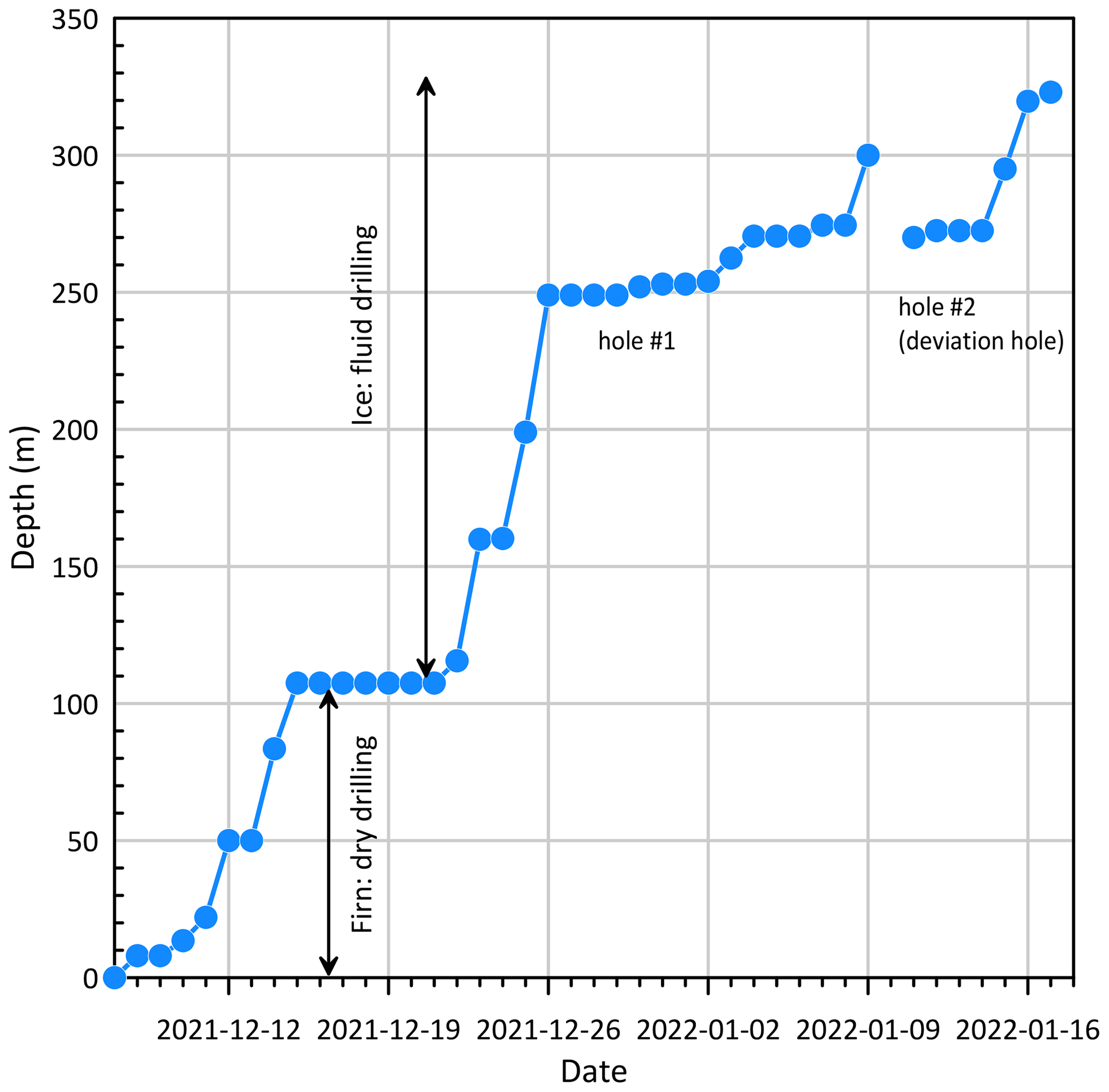
Overall, the improvements made for the 2021/22 season produced the expected results. Drilling from below the casing at 107 m to the previous depth of 250 m went smoothly in 4 work days (Fig. 13).
First, the hydraulic hose gave off fine greasy, flaky dirt, which tended to clog valves and the flux controller. After days of struggling, we finally heated and flushed the entire hose for many hours and were able to reduce it to a minor problem. However, we could not determine the origin of this dirt and why we did not observe it 2 years earlier, when we had used the same hose. The second problem was a too small holding torque of the drill's anti-torque. With the higher torque of the new motor we obviously exceeded the holding limit of the spring-loaded blades. Previously, we had only tested the anti-torque in −30 ∘C ice, where we observed ample margin. Additional tests on site showed a rapid decrease in torque in the colder, harder ice. We then added the spare anti-torque as a second one and improved spring load and edge geometry for maximum torque. The rotation of the anti-torque repeatedly caused problems in penetration and also deformed the borehole after a few attempts to initiate drilling at the same depth.
The third problem was the friction of the hydraulic hose in the drill hole. Friction coefficients μ on ice at −50 ∘C are much higher than near the melting point, with μ ≈ 0.25 for our Hytrel hose. The drilling fluid has no lubrication effect. On contrary it slightly increases friction compared to the dry case. As the RADIX drill has a very small diameter it bends much more easily than a larger-sized drill, and therefore the curvature radius of the hole is potentially smaller. Especially during phases with difficult penetration, the deviations from a straight hole tend to be larger.
Friction amplifies the force on a flexible string that is wound on an object, and the amplification grows exponentially, following the Euler–Eytelwein or capstan equation: force amplification = exp (α×μ), where α is the wrap angle (Euler, 1769; Eytelwein, 1832). This means that a slight resistance at one end of the hose, through cumulative curvature of the hose, can ultimately completely stop the movement of the hose. This situation was reached at around 300 m depth.
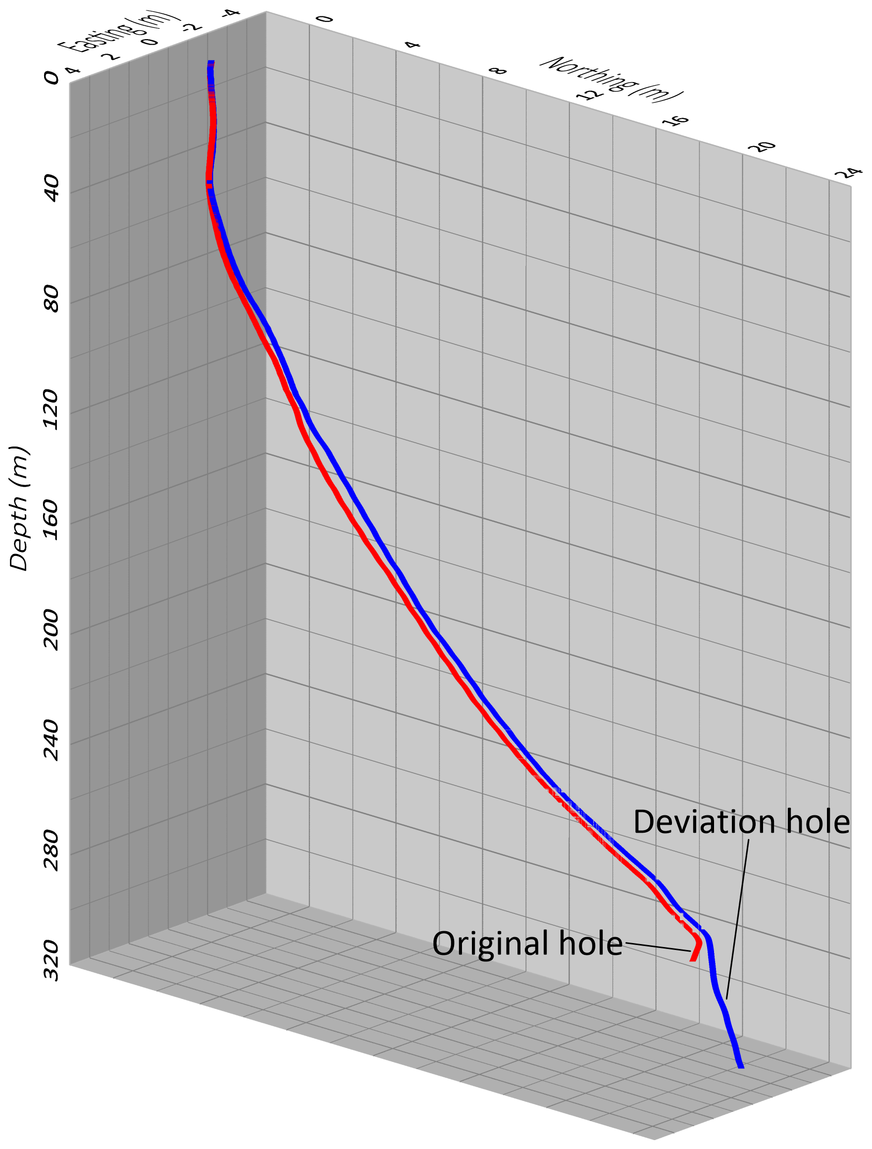
Figure 14The 3-D orientation of the Little Dome C 2021/22 boreholes. Down to a depth of 270 m, where the records are from the same hole, the difference between the red and blue curve indicates the uncertainty in the determination of the position based on the logger data.
After initially reaching 300 m depth we were not able to lower the drill beyond 280 m. Hole logging showed a sharp turn at 270 m depth, and the logger could not be lowered below 278 m due to another sharp bending. We decided to start a deviation hole at 270 m depth. After reaming a straight starting ramp using a countersink with modified, aggressive outer cutting edges, we could successfully initiate the deviation hole with the normal RADIX drill. A 3-D plot of the original and deviation hole are shown in Fig. 14. However, at 324 m depth we encountered the same situation, where penetration was no longer possible due to too high friction in the hole.
Subsequent logging stopped at 316 m where the logger would not further slide down. When pulling the logger up, it got caught at this depth but became free after pulling close to the maximum strength of the fiber-optic cable. This was an indication that the capstan effect could cause severe problems in retrieving a sonde that is even only slightly caught in the hole by reducing the force transmitted to the sonde to nearly zero.
We estimate a total wrap angle of about 90∘ from 110 to 310 m depth, based on the hole logging data. With a friction coefficient of 0.25, this yields a friction amplification of about 1.5. A 50 % increase in friction is substantial for the RADIX drill that is nearly weightless in fluid.

Figure 15Little Dome C 2021/22 hole inclination (324 m hole): blue marks downward logging; orange marks upward logging. The noise on the order of 1∘ on the submeter scale is caused by the acceleration (shaking) when lowering and raising the logger.
Figure 15 shows the borehole inclination including the deviation drilling beyond 270 m. The casing ends with an inclination of 6 to 7∘. We observe a decreasing trend to 5∘ at a depth of 210 m. The oscillations are a sign of a corkscrewing hole with a full turn at approximately 6.5 m intervals. Drilling at these depths was smooth, and the decrease in inclination could be the result of the auto-correction of verticality by the centering knobs. Below 210 m penetration was slower, which is a sign of increasing anti-torque rotation. Also, the corkscrewing pitch decreased to about 4 m at 255 m. At that depth we often had anti-torque rotation, and several times we drilled a few meters without anti-torque and rotary union (torque taken by hydraulic hose) in order to reestablish a clean hole for the anti-torque, resulting in a rapid increase in inclination.
Between 266 and 272 m the inclination decreased from 11 to 2∘. Rather than an effect of the auto-correction we think that this decrease is the result of drilling along a big helix that was initiated by the previous penetration problems. Below that depth the inclination shown in Fig. 15 is from the deviation hole. Here we have set the centering knobs 0.3 m higher up because we suspected too high side force on the drill head resulting in bending the lower part of the drill bit with a positive feedback on the side force resulting in even stronger bending. By moving the centering knobs to a higher position we allow for more freedom to the lower end of the drill but lose auto-correcting of verticality. Still the inclination of the hole remained rather low in the deviation hole, and we did not observe oscillations as before.
Capabilities and limitations of the present configuration are the following:
-
A 40 mm firn drill permits drilling in semi-continuous mode into the solid ice for placing a casing into a vacuum-cleaned hole.
-
A lightweight single-piece pipe serves as casing and is sealed by a rubber packer inflated with compressed air. The compressed air is prepared on site with a breathing-air compressor.
-
A fluid system powers the RADIX drill by means of a triplex high-pressure piston pump. The fluid is recycled through various filtering stages.
-
A 3100 m hydraulic hose on an electric winch provides enough depth capacity for drilling through the entire polar ice sheet at most sites.
-
The main drill is driven by a full metal Moineau motor (positive displacement mud motor) with 1.6 N m torque. It is flow- and pressure-controlled and housed in a 15 mm pipe.
-
A thread-cutting drill bit cuts a 20 mm hole at a nominal speed of 10 mm s−1.
-
Ice cuttings are transported with the drill fluid to the surface and can be sampled as needed for further analysis.
-
A deviation hole can be started as necessary at depths with elevated hole curvature.
-
A battery-powered logger is deployed separately on a fiber-optic cable. It transmits in “real time” temperature, 3-D acceleration, the 3-D magnetic field and dust in the surrounding ice. The latter could not yet be fully tested because it requires bubble-free ice, which is found only below the bubble-clathrate transition.
-
The main limitation of the RADIX system as used for the Little Dome C drilling for 2021/22 is its restricted depth capability, due to too high friction in the hole.
-
Presently, the system needs too frequent maintenance requiring hoisting the drill to the surface. The frequent spooling of the hose additionally lifts and spills much of the drill fluid to the surface.
The limiting factor for drilling deeper holes is the high friction / weight ratio and/or small curvature radii of the borehole. In order to lower the friction / weight ratio, one could make the drill itself heavier by adding more tungsten extension tubes. However a longer drill would be uncomfortable for handling in the present shelter. Another practicable change to the drill would be to increase the diameter, which would however infer a larger hole diameter and a whole cascade of changes, in particular abandoning the concept of minimum weight and minimum resources. Another possibility of increasing the weight would be to use a different material for the hydraulic hose. In the present configuration the total weight of the hose immersed in fluid with a density of 930 kg m−3 is approximately 700 N. An armor of steel instead of aramid or even a plain steel tube would add sufficient weight for moving the drill down. However, a heavier hose or plain tube would entail major changes to the winching device with the consequence of stronger, bulkier equipment.
Concerning lowering the friction in the hole, there are two main sources of friction, the hose and the anti-torque. As stated above, in order to maintain the low-weight concept, we must stay with a plastic hose. We have found that the friction coefficients of common plastics on ice at −50 ∘C are rather similar, and since friction amplification increases exponentially with the wrap angle, a change of a few percent in the friction coefficient would not make much difference.
At Little Dome C, we had to use a double anti-torque with substantial spring loads on the skates to get sufficient torque. The axial friction of the anti-torque made up a substantial part of the weight of the drill, and still the torque was marginally sufficient for drilling. For a future version of RADIX the anti-torque system must provide higher torque while reducing the axial friction.
A reduction in the total wrap angle offers probably the greatest potential for improvement. As flexibility of an object does not scale linearly with its dimension, small objects tend to flex excessively, as does RADIX, potentially producing curved holes. A larger-diameter drill would help, but this would, as mentioned, entail changes toward heavier equipment and require more drilling fluid. In order to reduce the wrap angle with the present dimensions, we must introduce specific measures. These include geometric considerations for the design of the drill and bit and reducing the flexibility of the lower part of the drill in order to avoid helical paths of the drill hole.
No data sets were used in this article.
JS developed and designed the overall concept of RADIX. RW and SM improved design details and realized mechanical components. JS, TS and RM participated in field campaigns in Greenland and Antarctica and provided photographs. JS wrote the manuscript with contributions from all co-authors.
The contact author has declared that none of the authors has any competing interests.
Publisher's note: Copernicus Publications remains neutral with regard to jurisdictional claims in published maps and institutional affiliations.
This article is part of the special issue “Ice core science at the three poles (CP/TC inter-journal SI)”. It is not associated with a conference.
We would like to thank Hanspeter Moret for implementing the controller software. We are grateful to Jörg Pierer, Centre Suisse d'Electronique et de Microtechnique, for providing an extensive simulation of the light scattering on dust particles in ice. The logger electronics were realized with great care by Spacetek (https://www.spacetek.ch, last access: 27 February 2023).
This research has been supported by the Swiss National Science Foundation (SNSF) (project nos. 159563, 172745 and 200492), Frederik Paulsen of Ferring International and the Fondation Prince Albert II de Monaco (project no. 2436).
This paper was edited by Jay Johnson and reviewed by John Goodge and Julius Rix.
Alemany, O., Chappellaz, J., Triest, J., Calzas, M., Cattani, O., Chemin, J. F., Desbois, Q., Desbois, T., Duphil, R., Falourd, S., Grilli, R., Guillerme, C., Kerstel, E., Laurent, B., Lefebvre, E., Marrocco, N., Pascual, O., Piard, L., Possenti, P., Romanini, D., Thiebaut, V., and Yamani, R.: The SUBGLACIOR drilling probe: concept and design, Ann. Glaciol., 55, 233–242, 2014.
Bay, R. C., Price, P. B., Clow, G. D., and Gow, A. J.: Climate logging with a new rapid optical technique at Siple Dome, Geophys. Res. Lett., 28, 4635–4638, https://doi.org/10.1029/2001GL013763, 2001.
Clow, G. D. and Koci, B.: A Fast Mechanical-Access Drill for Polar Glaciology, Paleoclimatology, Geology, Tectonics, and Biology, Mem. Natl. Inst. Polar Res., 56, 5–37, 2002.
Euler, L.: Remarques sur l'effet du frottement dans l'équilibre, Mémoires de l'académie des sciences de Berlin, 18, 265–278, 1769.
Eytelwein, J. A.: Von der Reibung eines um einen unbeweglichen Cylinder gespannten Seiles, in: Handbuch der Statik fester Körper, Mit vorzüglicher Rücksicht auf ihre Anwendung in der Architektur, Zweite Auflage, Erster Band, 434–437, Berlin, Gedruckt und verlegt bei G. Reimer, https://doi.org/10.1515/9783111687353, 1832.
Goodge, J. W., Severinghaus, J. P., Johnson, J., Tosi, D., and Bay, R.: Deep ice drilling, bedrock coring and dust logging with the Rapid Access Ice Drill (RAID) at Minna Bluff, Antarctica, Ann. Glaciol., 62, 324–339, 2021.
Potenza, M. A. C., Albani, S., Delmonte, B., Villa, S., Sanvito, T., Paroli, B., Pullia, A., Baccolo, G., Mahowald, N., and Maggi, V.: Shape and size constraints on dust optical properties from the Dome C ice core, Antarctica, Sci. Rep.-UK, 6, 28162, https://doi.org/10.1038/srep28162, 2016.
Rix, J., Mulvaney, R., Hong, J. L., and Ashurst, D.: Development of the British Antarctic Survey Rapid Access Isotope Drill, J. Glaciol., 65, 288–298, 2019.
Schwander, J., Marending, S., Stocker, T. F., and Fischer, H.: RADIX: a minimal-resources rapid-access drilling system, Ann. Glaciol., 55, 34–38, 2014.
Yoshino, M.: Effects of External Hydrostatic Pressure on Orthogonal Cutting Characteristics, 44th North American Manufacturing Research Conference, Namrc 44, 27 June–1 July 2016, Blacksburg, Virginia, USA, 5, 1308–1319, https://doi.org/10.1016/j.promfg.2016.08.102, 2016.
- Abstract
- Introduction
- RADIX components (2021 version)
- Typical workflow for the use of RADIX
- Polar field tests, 2015 to 2022
- Critical appraisal of the latest RADIX deployment, 2021/22
- Further developments and conclusions
- Data availability
- Author contributions
- Competing interests
- Disclaimer
- Special issue statement
- Acknowledgements
- Financial support
- Review statement
- References