the Creative Commons Attribution 4.0 License.
the Creative Commons Attribution 4.0 License.
 | 27 May 2021
Creep and fracture of warm columnar freshwater ice
Iman E. Gharamti
John P. Dempsey
Arttu Polojärvi
Jukka Tuhkuri
This work addresses the time-dependent response of 3 m×6 m floating edge-cracked rectangular plates of columnar freshwater S2 ice by conducting load control (LC) mode I fracture tests in the Aalto Ice Tank of Aalto University. The thickness of the ice plates was about 0.4 m and the temperature at the top surface about −0.3 ∘C. The loading was applied in the direction normal to the columnar grains and consisted of creep/cyclic-recovery sequences followed by a monotonic ramp to fracture. The LC test results were compared with previous monotonically loaded displacement control (DC) experiments of the same ice, and the effect of creep and cyclic sequences on the fracture properties were discussed. To characterize the nonlinear displacement–load relation, Schapery's constitutive model of nonlinear thermodynamics was applied to analyze the experimental data. A numerical optimization procedure using Nelder–Mead's (N-M) method was implemented to evaluate the model functions by matching the displacement record generated by the model and measured by the experiment. The accuracy of the constitutive model is checked and validated against the experimental response at the crack mouth. Under the testing conditions, the creep phases were dominated by a steady phase, and the ice response was overall elastic–viscoplastic; no significant viscoelasticity or major recovery was detected. In addition, there was no clear effect of the creep loading on the fracture properties at crack growth initiation: the failure load and crack opening displacements.
- Article
(1767 KB) - Full-text XML
- BibTeX
- EndNote


Understanding the deformation and fracture processes of columnar freshwater ice is important in many engineering problems. For example, freshwater ice sheets fracture when in contact with ships, river ice fractures during interaction with bridge piers, and thermal cracks form in lakes and reservoirs. Deformation and fracture processes of freshwater ice are highly dependent on temperature, strain rate, sample size, grain type, and grain size. Qualitatively, high temperature and low strain rate lead to viscous behavior and ductile fracture; low temperature and high strain rate lead to elastic behavior and brittle fracture (Gharamti et al., 2021). However, quantitatively these relations are not well known.
As the response of freshwater ice is time-dependent, a general constitutive model should incorporate elastic (immediate and recoverable), viscoelastic (or delayed elastic, time-dependent, and recoverable), and viscoplastic (time-dependent and unrecoverable) components (Jellinek and Brill, 1956; Sinha, 1978). The importance of each component depends on the problem studied. For example, thermal deformations of ice in dams can have a timescale of a few days and creep behavior dominates. In ice–structure interaction problems, the timescale of interest is often seconds and hours, so all three components of deformation need to be modeled.
This paper reports results from laboratory experiments which were conducted to study the time-dependent response and fracture of columnar freshwater ice. The work is directly relevant to a number of practical problems (Ashton, 1986) but has also general relevance in ice research by studying the coupled creep and fracture in a quasi-brittle material. Unless just short timescales are involved, where only elastic response is relevant, the creep deformations must be modeled to obtain the true fracture behavior. In materials with time-dependent properties, the fracture and creep responses are coexistent.
The time-dependent behavior of freshwater ice has been addressed with great attention, and several constitutive models were developed (Michel, 1978; Sinha, 1978; Le Gac and Duval, 1980; Ashby and Duval, 1985; Sunder and Wu, 1989; Mellor and Cole, 1983; Cole, 1990; Duval et al., 1991; Sunder and Wu, 1990; Abdel-Tawab and Rodin, 1997; Santaoja, 1990). Constitutive laws can be phenomenological or micromechanical. Micromechanical modeling in ice faces challenges because the characterization of the microscopic mechanisms of ice deformation is still inadequate (Abdel-Tawab and Rodin, 1997).
Phenomenological laws are classified into two groups. The first group is empirically based relations (Sinha, 1978; Schapery, 1969). Their equations relate macroscopic variables: stress/load, strain/displacement, and time. They do not contain state variables that describe the internal state of the material and are valid only for constant stress/load. The functions in these models can be easily calibrated to simulate the experiments. The second group of phenomenological models starts from physically based models involving internal state variables (dislocation density, internal stresses reflecting hardening, etc.); they develop differential equations for the evolution of these variables with time and quantify the dependence of these variables on stress, temperature, and strain (Le Gac and Duval, 1980; Sunder and Wu, 1989, 1990; Abdel-Tawab and Rodin, 1997). These models provide insights into the microscopic mechanisms taking place, and the state variables describe the deformation resistance offered by changes in the microstructure of the material. However, they require a proper identification of the deformation mechanisms.
The effect of time-dependent loading on the strength of freshwater ice has been examined in the literature. Subjecting freshwater ice to cyclic loading apparently leads to a significant increase in the tensile, compressive, flexural strength, and fracture toughness of that ice (Murdza et al., 2020; Iliescu et al., 2017; Iliescu and Schulson, 2002; Jorgen and Picu, 1998; Rist et al., 1996; Cole, 1990). On the other hand, no detailed investigation of the effect of creep and cyclic loading on the fracture properties of freshwater ice has been conducted in the past.
Laboratory experiments were conducted to measure the time-dependent response and fracture behavior of 3 m×6 m floating edge-cracked rectangular plates of columnar freshwater S2 ice, loaded in the direction normal to the columnar grains. The ice studied was warm, and the temperature at the top surface of the samples was about −0.3 ∘C. Compared to earlier studies with freshwater ice, the samples were large (3 m×6 m) and very warm. A program of five load control (LC) mode I fracture tests was completed in the test basin (40 m square and 2.8 m deep) at Aalto University. Creep/cyclic-recovery sequences were applied below the failure loads, followed by monotonic ramps leading to complete fracture of the specimen. The LC results were compared with the fracture results of monotonically loaded displacement control (DC) tests of the same ice (Gharamti et al., 2021), and the effects of the creep and cyclic sequences on the fracture properties were analyzed.
The constitutive modeling used in this paper was presented by Schapery (1969) and applied to polymers. Schapery's model belongs to the first phenomenological group and originates from the theory of nonlinear thermodynamics. This study presents the first attempt to use Schapery's model for freshwater ice. The choice of this model for freshwater ice is motivated by the fact that the model was successfully applied to saline ice (Schapery, 1997; Adamson and Dempsey, 1998; LeClair et al., 1999, 1996) with encouraging results. The model accurately described the deformation response during load/unload applications over varying load profiles.
The experiments in this study aim to assess the time-dependent nature of warm columnar freshwater S2 ice. In particular, the study aims to examine (1) the extent to which the elastic, viscoelastic, and viscoplastic components contribute to the ice deformation as defined through the crack mouth opening displacement; (2) the effects of the testing conditions on the creep stages (primary/transient and steady state/secondary) present in the ice; (3) the effects that creep and cyclic sequences have on the fracture properties – i.e., failure load and crack growth initiation displacements; and (4) the ability of Schapery's nonlinear constitutive model to predict the experimental response.
The rest of the paper is structured as follows. In Sect. 2, a description of the experimental setup, testing conditions, and the applied loading profile is presented. Section 3 introduces Schapery's model, which is used to analyze the experiments. In Sect. 4, the experimental and model results are summarized and analyzed. Section 5 concludes the paper.
Figure 1Specimen geometry. Edge-cracked rectangular plate of length L, width H, and crack length A0.
Figure 2(a) Temperature profile. Each data point represents the average of measurements taken at the same depth of different ice cores throughout the 1-month duration of the test program. (b) Grain size distribution. Each data point is measured from one thin section.
2.1 Experimental details
The ice specimens tested were 3 m×6 m rectangular plates, cut from a 40 m×40 m parent sheet, with a thickness of 340–410 mm, and instrumented as shown in Fig. 1. The experiments were conducted at an ambient temperature of −2 ∘C. The ice was columnar freshwater S2 ice having a mean grain size of 6.5 mm (Fig. 2b). The temperature at the top surface was about −0.3 ∘C, as shown in Fig. 2a. An edge crack of length A0 (A0≈0.7 L) was cut and tip-sharpened in each ice specimen. The response of the ice was monitored by using a number of surface-mounted linear variable differential transducers (LVDTs). LVDTs were placed at five different locations along the crack to measure directly the crack opening displacements. Figure 1 labels these positions as CMOD, COD, NCOD1, NCOD2, and NCOD3 for the crack mouth, intermediate crack, 10 cm behind the initially sharpened tip, 10 cm ahead of the tip, and 20 cm ahead of it, respectively. A hydraulically operated device was inserted in the mouth of the pre-crack to load the specimen horizontally, in the direction normal to the columnar grains, with a contact loading length of 150 mm, denoted by D in Fig. 1. The tests were load controlled by a computer-operated closed-loop system that also recorded the displacement measurements. Creep/cyclic-recovery sequences were applied below the failure loads, followed by monotonic ramps leading to complete fracture of the specimen. The loading rate used is similar to that used in earlier sea ice studies (LeClair et al., 1999; Adamson and Dempsey, 1998) and thus allows for comparison of these two materials. The global behavior of the crack propagation was straight through the gauges. Detailed description of the experimental setup, ice growth, microstructure, and fractographic analysis is provided in Gharamti et al. (2021).
2.2 Creep-recovery and monotonic loading profile
In two tests, ice specimens were subjected to creep-recovery loading followed by a monotonic fracture ramp. The creep-recovery sequences consisted of four constant load applications, separated by zero-load-recovery periods. Each sequence was composed of alternating load/hold and release/recovery periods. Creep phases were applied at load levels of 0.4, 0.8, 1.2, and 0.4 kN, as given by the loading signal in Fig. 3a. The loads were chosen low enough to avoid crack propagation and failure of the specimen. Each load–hold–unload was applied in the form of a trapezoidal wave function to avoid instantaneous load jump and drop; the loading was applied in approximately 10 s and released in approximately 10 s. The slopes of the wave on loading and load release were 0.04, 0.08, and 0.12 kN s−1 for the 0.4, 0.8, and 1.2 kN load levels, respectively.
Figure 3Loading consisting of (a) creep-recovery and (b) cyclic sequences followed by a monotonic fracture ramp. The number above each segment indicates the duration in seconds.
Once at the desired hold level, the load was kept constant for a predetermined time interval. The load intervals were multiples of the hold interval for the 0.4 kN load level, Δt1=126 s. For the 0.8 and 1.2 kN load levels, the time interval was doubled and quadrupled: 2Δt1=252 s and 4Δt1=504 s, respectively. The four zero-load-recovery periods, separating the creep load periods, were also a function of Δt1. Three recovery periods were held at the zero-load level for 5Δt1=630 s, but the last recovery period was maintained for a longer interval of 10Δt1=1260 s.
Immediately following the creep and recovery loading sequences, the specimen was loaded monotonically to failure on a load-controlled linear ramp. The ramp up to the peak load and unloading were each applied over an interval of Δt1.
2.3 Cyclic-recovery and monotonic loading profile
In three tests, ice specimens were loaded with cyclic-recovery sequences followed by a fracture ramp, as shown in Fig. 3b. The cyclic-recovery loading consisted of three sequences, with each being composed of four fluctuating loads, at the levels of 0.4, 0.8, and 1.2 kN. Each cyclic sequence continued for a constant time interval Δt2=480 s. The slopes of the wave on the loading and load release were , , and kN s−1 for the 0.4, 0.8, and 1.2 kN load levels, respectively. The 0.4, 0.8, and 1.2 kN cyclic load periods were followed by zero-load-recovery periods of 1.25Δt2=600 s, 1.25Δt2=600 s, and 2.5Δt2=1200 s, respectively.
At the completion of the cyclic-recovery loading sequences, the specimen was loaded to failure by a monotonic linear ramp. The ramp up to the peak load and unloading were each applied over an interval of 0.25Δt2=120 s.
The model applied in this section to characterize the nonlinear viscoelastic/viscoplastic response of S2 columnar freshwater ice was presented by Schapery; it was used to model the time-dependent mechanical response of polymers in the nonlinear range under uniaxial stress-strain histories (Schapery, 1969). Schapery's stress-strain constitutive equations are derived from nonlinear thermodynamic principles and are very similar to the Boltzmann superposition integral form of linear theory (Flügge, 1975). Schapery's model represents the material as a system of an arbitrarily large number of nonlinear springs and dashpots.
The equations in this section are presented in terms of load and displacement instead of the original stress-strain relations. The notations of the original equations in Schapery (1969) are modified to bring out similarity between all the equations in the paper.
When the applied loads are low enough, the material response is linear. For an arbitrary load input, P=P(t) applied at t=0, Boltzmann's law approximates the load by a sum of a series of constant load inputs and describes the linear viscoelastic displacement response of the material using the hereditary integral in a single integral constitutive equation. The Boltzmann superposition principle states that the sum of the displacement outputs resulting from each load step is the same as the displacement output resulting from the whole load input. If the number of steps tends to infinity, the total displacement is given as
where C0 is the initial, time-independent compliance component and ΔC(t) is the transient, time-dependent component of compliance.
Turning now to nonlinear viscoelastic response, Schapery developed a simple single-integral constitutive equation from nonlinear thermodynamic theory, with either stresses or strains entering as independent variables (Schapery, 1969). Using load as the independent variable, the displacement response under isothermal and uniaxial loading takes the following form:
where C0 and ΔC are the previously defined components of the Boltzmann principle; ψ and ψ′ are the so-called reduced times defined by
and g0, g1, g2, and aP are nonlinear functions of the load. Each of these functions represents a different nonlinear influence on the compliance: g0 models the elastic response, g1 models the transient response, g2 models the loading rate, and aP is a timescale shift factor. These load-dependent properties have a thermodynamic origin. Changes in g0,g1, and g2 reflect third- and higher-order stress dependence of the Gibbs free energy, and changes in aP are due to similar dependence of both entropy production and the free energy. These functions can also be interpreted as modulus and viscosity factors in a mechanical model representation. In the linear viscoelastic case, , and Schapery's constitutive Eq. (2) reduces to Boltzmann's Eq. (1).
Equation (2) contains one time-dependent compliance property, from linear viscoelasticity theory, ΔC, and four nonlinear load-dependent functions, , and aP, which reflect the deviation from the linear viscoelastic response, that need to be evaluated. Schapery's model uses experimental data to evaluate the material property functions in Eq. (2). Lou and Schapery outlined a combined graphical and numerical procedure to evaluate these functions (Lou and Schapery, 1971). In their work, a data-reduction method was applied to evaluate the properties from the creep and recovery data. Papanicolaou et al. proposed a method capable of analytically evaluating the material functions using only limiting values of the creep-recovery test (Papanicolaou et al., 1999). Numerical methods are also employed and are the most commonly used techniques; they are based on fitting the experimental data to the constitutive equation (LeClair et al., 1999). In the current study, a numerical-experimental procedure is adopted. An optimization procedure is applied using the Nelder–Mead (N-M) method (Nelder and Mead, 1965) to back-calculate the values that achieve the best fit between the model and the experimental data. To avoid multiple fitting treatments of data and account for the mutual dependence of the functions, the properties were determined from the full data. This avoided errors that may result from separating the data into parts and estimating the functions independently from different parts.
Schapery later updated his formulation (Schapery, 1997). He added a viscoplastic term to account for the viscoplastic response of the material and stated that the total compliance can be represented as the summation of elastic, viscoelastic, and viscoplastic components. Adamson and Dempsey applied Schapery's updated constitutive equation to model the crack mouth opening displacement of saline ice in an experimental setup similar to the current study (Adamson and Dempsey, 1998). The theory represents the displacement at the crack mouth (δCMOD) as the sum of elastic, viscoelastic, and viscoplastic components:
where
In the above equations, ψ and ψ′ are defined in Eq. (3). g0, g1, g2, g3, and aP are nonlinear load functions to be determined. The coefficients Ce, Cve, and Cvp are the elastic, viscoelastic, and viscoplastic compliances, respectively. Schapery's equation has been developed for uniaxial loading. The response of the test specimen is dominated by the normal stresses at the direction normal to the x axis, ahead of the crack (Fig. 1). This stress state can be approximated as uniaxial in the same way as in beam bending; the stress is uniaxial tension at the crack tip and then changes linearly. Thus, Schapery's equations are used to analyze the experimental data. Few assumptions are applied at this point and are based on the choices made in Adamson and Dempsey (1998). For ice, the elastic displacement is linear with load; this immediately leads to g0=1. Schapery stated that if the instantaneous jump and drop in the displacement are equal (Schapery, 1969). Examination of the current data shows that this condition is not valid, and the functions need to be evaluated. Accordingly, the following approximations are employed:
From Eq. (3),
The viscoelastic compliance is assumed to follow a power law in time with a fractional exponent n. This gives
Incorporating each of these conditions, the total displacement is expressed as
where δCMOD, P, and t are in meters, newtons, and seconds, respectively. It follows from Eq. (11) that two unknown parameters (Ce and Cvp), one unknown constant (κ), and five unknown exponents (a, b, c, d, and n) need to be determined. As previously mentioned, the problem is optimized through the N-M technique, by minimizing the objective function ℱ given by the difference between the model and data, as shown in Eq. (12). The components of the total displacement were computed and optimized using MATLAB. A positive constraint was applied to the model variables. Initial guesses of the exponents on the load and time functions were assumed based on previous work on saline ice. The optimized values were then obtained by comparing the model response and the experimentally measured response over the full length of the test up to crack growth initiation.
where Mi and Di refer to the CMOD values given by the model (11) and the experimental data, respectively. is the Euclidean norm of a vector. N is the number of data points ( points). This problem is typically called a least-squares problem when using the Euclidean norm. It is a convex problem because ℱ is a convex function and the feasible set is convex. Thus, the optimization algorithm will converge to the global optimal solution.
As mentioned earlier, Schapery's model originated from the thermodynamic theory. The model is not physically based, and its parameters are not linked to the microstructural properties of the ice (dislocation density, grain size, etc.). In addition, the analysis does not account for the formation of a fracture process zone in the vicinity of the crack tip. Schapery's formulation models the experimental response until crack growth initiation and does not account for crack propagation.
This section presents the results measured and computed for the LC tests. The current results are compared with the fracture results of monotonically loaded DC tests of the same ice and same specimen size (3 m×6 m) (Gharamti et al., 2021). The main aim is to elucidate the effect of creep and cyclic sequences on the fracture properties.
Table 1Measured experimental data and computed results for the LC tests.

4.1 Effect of the creep and cyclic sequences on the fracture properties
Table 1 shows the measured and computed parameters for the LC experiments. Pmax is the measured peak load, which is also the failure load. tf represents the time to failure, computed from the fracture ramp. CMOD is measured at crack growth initiation. indicates the displacement rate at the crack mouth and is obtained by dividing CMOD by the failure time. Similarly, NCOD1 (see Fig. 1) represents the displacement at crack growth initiation near the initially sharpened crack tip. indicates the displacement rate in the vicinity of the tip and is obtained by dividing NCOD1 by the failure time.
Figure 4Experimental results for the (a) peak load Pmax, (b) crack mouth opening displacement CMOD, and (c) near-crack-tip opening displacement NCOD1 at crack growth initiation, as a function of time to failure tf for the monotonically loaded DC tests (Gharamti et al., 2021) and the creep/cyclic and monotonically loaded LC tests.
Figure 4 gives the results of the peak load Pmax, crack mouth opening displacement CMOD, and near-crack-tip opening displacement NCOD1 as a function of the loading time for the DC tests (Gharamti et al., 2021) and the current LC tests. In these subplots, first-order power-law fits were applied to the data of the DC tests. The LC values lie above, below, and along the DC fit. No clear effect of creep and cyclic loading on the fracture properties was detected.

Figure 5Measured load versus CMOD for the (a) DC tests (Gharamti et al., 2021), (b) LC tests, and (c) LC tests up to the peak load.
Figure 5a and b show the experimental load versus the crack opening displacement at the crack mouth for the DC and the LC tests, respectively. Figure 5c displays a magnified view of the fracture ramp of the LC tests. Comparing the failure loads of the DC and LC tests indicates that the failure loads, of tests with comparable loading rates, were similar. Therefore, in these experiments, the creep and cyclic sequences had no influence on the failure load.
Table 1 presents several elastic moduli for each test. The elastic moduli were calculated from the load–CMOD record following Sect. 4 of Gharamti et al. (2021). For the creep tests (RP15 and RP16), this procedure is repeated for the four creep cycles, resulting in E1, E2, E3, and E4, and for the fracture ramp, resulting in Ef. Similarly for the cyclic tests (RP17, RP18, and RP19), the moduli calculation was done for the last cycle of each cyclic sequence, giving steady-state moduli E1, E2, and E3, and for the fracture ramp, resulting in Ef. Some of the values are missing, caused by the fact that the initial portion of the associated load–CMOD curve was very noisy. The values of the elastic moduli calculation for the creep/cyclic sequences and fracture ramps were similarly linear upon load application, as shown by the loading slope in Fig. 5c and Fig. 6a and b. This linearity justifies the choice of g0=1 in the elastic CMOD component in Eq. (5).

Figure 6Load versus CMOD over the (a) creep-recovery cycles for RP15 and the (b) cyclic-recovery sequences for RP17. (c) Schematic illustration of the hysteresis load-displacement diagram. The whole of the hysteresis loop area is the energy loss per cycle. The dashed area is the part of that total that is due to the viscoelastic mechanism and the rest is due to viscous processes.
Table 1 in Gharamti et al. (2021) presents the elastic modulus (ECMOD) calculated at the crack mouth for the DC tests; ECMOD is similar to Ef in Table 1 here; both values lie within the same range. Therefore, the creep and cyclic sequences preceding the fracture ramp did not affect the load–CMOD prepeak behavior. However, the sequences affected the postpeak response as can be distinguished from Fig. 5b, which displays a longer decay behavior than Fig. 5a. The gradual decay of the load portrays the time dependency in the behavior of freshwater ice.
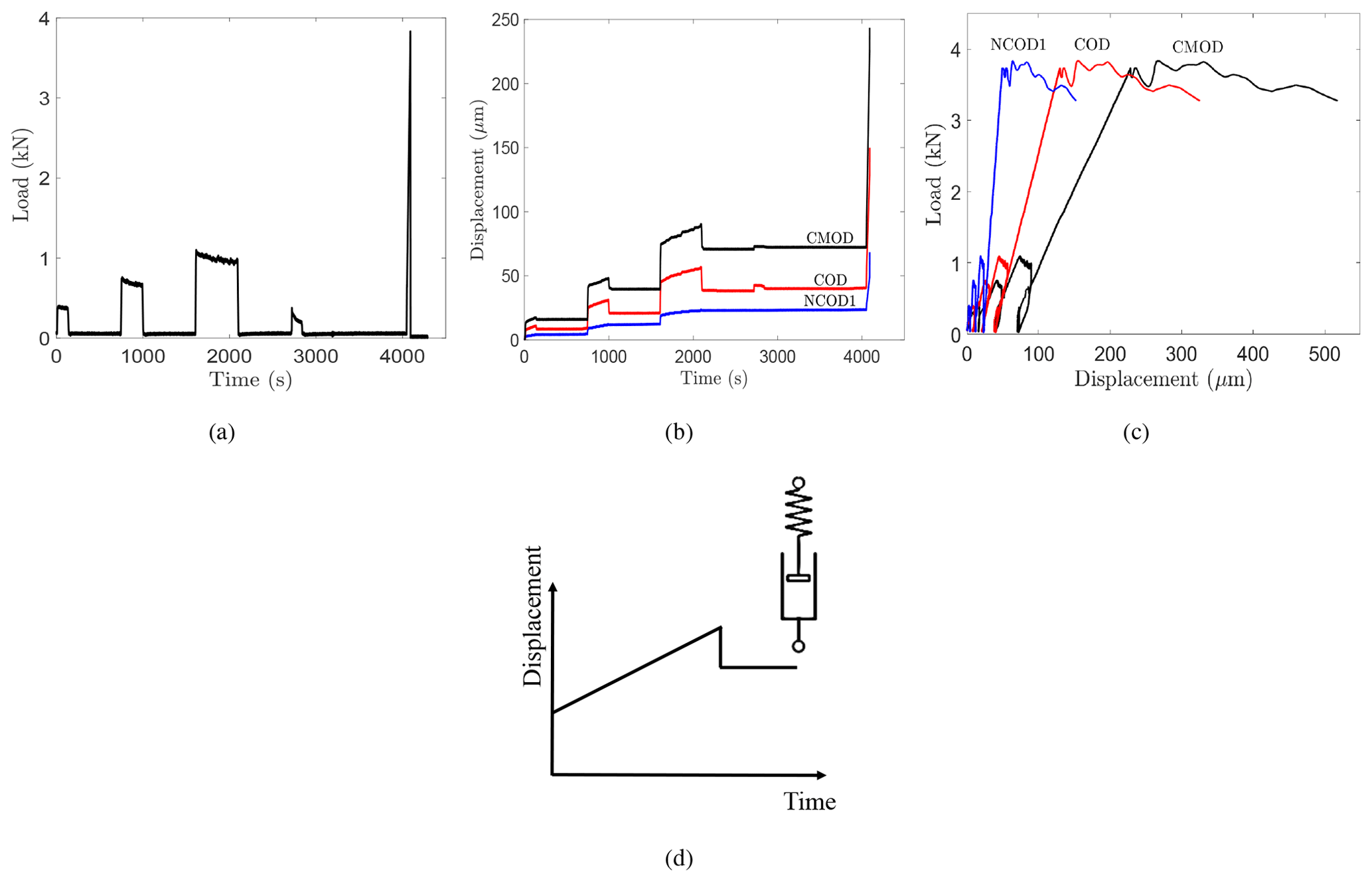
Figure 7Experimental results for RP16. (a) Load at the crack mouth; see Fig. 1. (b) Displacement–time records. (c) Load–displacement record. (d) Typical response of a Maxwell model, consisting of a nonlinear spring and nonlinear dashpot, to a constant load step.
4.2 Ice response under the testing conditions
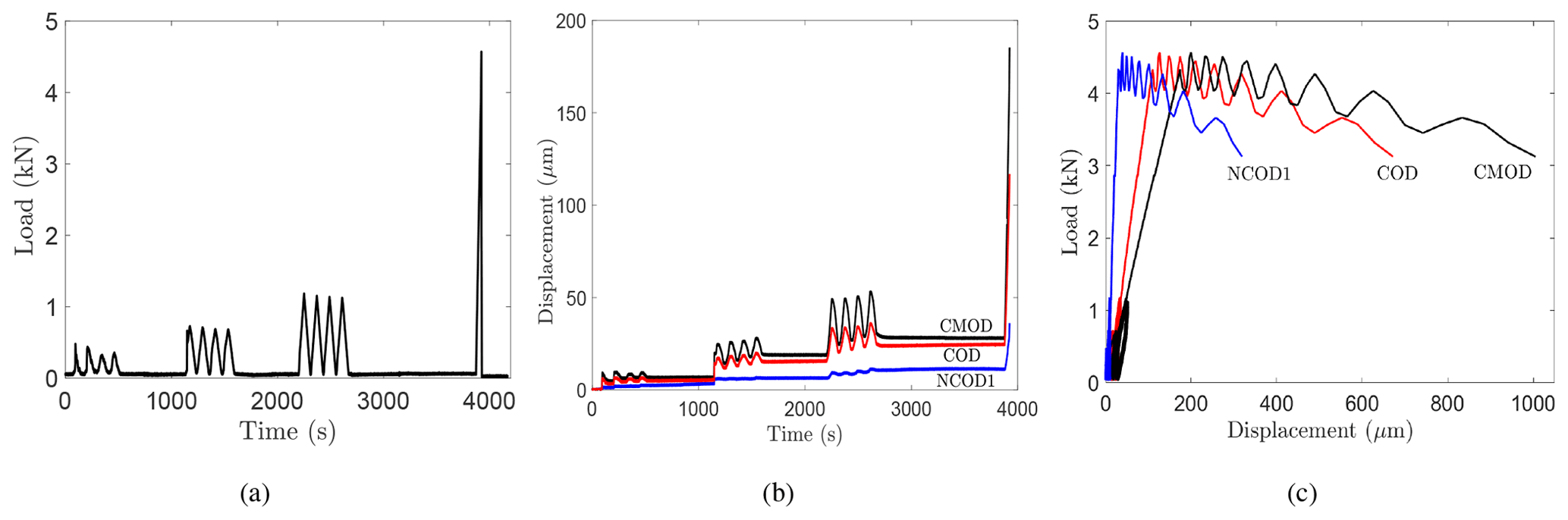
Figure 7 shows the experimental results for RP16: the applied load and the crack opening displacements at the crack mouth (CMOD), halfway of the crack (COD), and 10 cm behind the tip (NCOD1) (see Fig. 1). Similarly, Fig. 8 shows the experimental response for RP17. The time-dependent nature of the ice response is evident. A complete load–CMOD curve was obtained during loading and unloading for each test of Table 1, indicating stable crack growth.
It is clear from Figs. 7b and 8b that the CMOD, COD, and NCOD1 displacements were composed mainly of elastic and viscoplastic components. No significant viscoelasticity was detected in the displacement–time records for all the tests. The primary (transient) creep stage was almost absent or instantaneous. The load sequences were characterized by a non-decreasing displacement rate at all levels. The displacement–time slope was linear and constant, indicating that the secondary/steady-state creep regime dominated during each load application. Although the recovery time was longer than the loading time, ≥1.25Δt1 (creep test, Fig. 3a and Sect. 2.2) and ≥1.25Δt2 (cyclic test, Fig. 3b and Sect. 2.3), the recovery (unload) phases consisted mainly of an elastic recovery (instantaneous drop) and unrecovered viscoplastic displacement. The behavior as observed resembles the response of a Maxwell model composed of a series combination of a nonlinear spring and nonlinear dashpot (Fig. 7c). There is no delayed elastic recovery, but there is the elastic response and a permanent deformation.
Figure 6a and b support the same analysis. Unlike the viscoelastic response (Fig. 6c), which displays no residual displacement in the loading and unloading hysteresis diagram, the current load–CMOD plots showed large permanent displacement after each loading cycle. This concludes that the response of columnar freshwater S2 ice in these tests was overall elastic–viscoplastic.
4.3 Nonlinear modeling analysis
The nonlinear theory, outlined in Sect. 3, was used to analyze the experiments. Modeling the viscoelastic term (second term of Eq. 11) proved to be very challenging. Instead, a simplified version was modeled by setting . The results of the initial optimization trials confirmed the previous analysis; the viscoelastic component had no effect on the final fit between the data and the model. The optimization algorithm fine-tuned κ (Eq. 11) to a very small number (10−18), indicating that the best model–data fit is attained when the viscoelastic term goes to zero.

The final optimization runs were carried out by considering the elastic and viscoplastic components (first and last terms of Eq. 11) only. This resulted in two parameters, Ce and Cvp, and one exponent, c, that need to be optimized. The optimization converged results are given in Table 2: Ce, Cvp, and c. For all the tests, the percent reduction of the objective function exceeded 95 %, and about 110 iterations were needed to reach convergence. A value of c=1 for the viscoplastic load function provided the best fit between the model and the experiment at all load levels over the total experimental time up to the peak load. The final compliance values of the elastic and viscoplastic components were in the ranges 1.8– mN−1 and 0.2– mN−1 s−1. respectively.
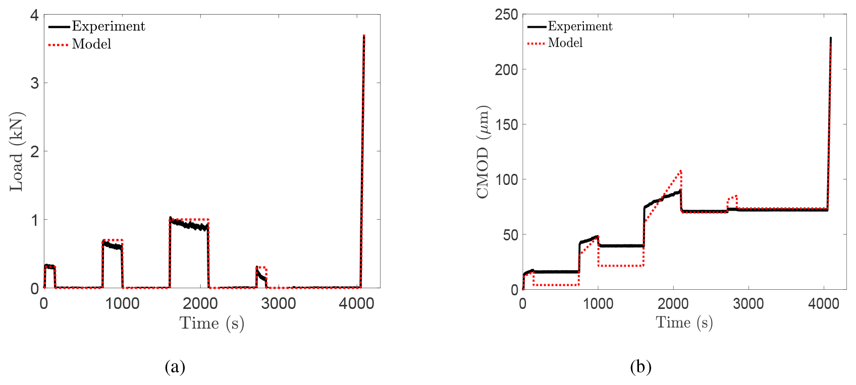
Figure 9Experimental and model results for RP16. (a) Load at the crack mouth; see Fig. 1. (b) CMOD–time records.
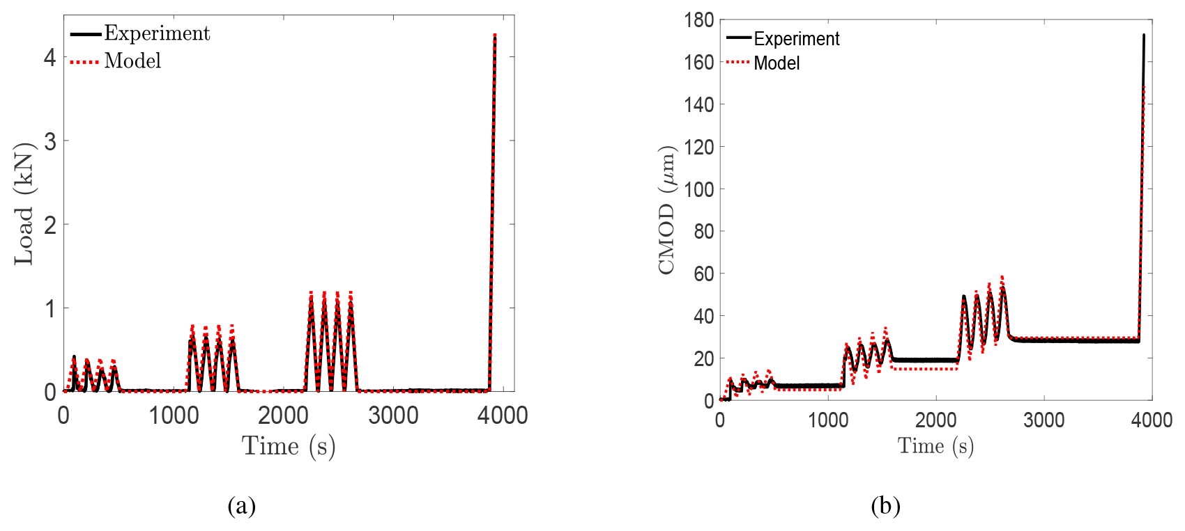
Figure 10Experimental and model results for RP17. (a) Load at the crack mouth; see Fig. 1. (b) CMOD–time records.
Figures 9 and 10 give the model results, obtained using Eqs. (4)–(10), and the experimental results for experiments RP16 and RP17, respectively. Figure 9a and b show the measured load and the load applied to the model and the measured CMOD–time record compared to the response of the model, respectively, for RP16. Figure 10 shows similar plots for experiment RP17. Test RP17 showed an excellent model–experiment fit for the three cyclic-recovery sequences over the load and unload periods. The model succeeded in following the increasing and decreasing load levels and the corresponding recovery phases. The experimental response for the creep-recovery test RP16 appeared to generally conform to the model results, but the model overestimated the recovery displacement in the first two cycles. It is unclear to the authors why the model did a better job in fitting the cyclic-recovery than the creep-recovery sequences. This probably hints at some mechanisms that took place in the creep-recovery tests and are not accounted for by Schapery's model. Schapery's model has been tested for creep-recovery sequences of saline ice with an increasing load profile (Schapery, 1997; Adamson and Dempsey, 1998; LeClair et al., 1999, 1996). This is the first application of the model with a load profile of increasing and decreasing load levels (Fig. 3).
Considering the fracture ramp, Schapery's nonlinear equation succeeded in modeling the monotonic displacement response up to crack growth initiation perfectly well for all the tests. As previously mentioned, the model does not account for crack propagation, so modeling was applied until the peak load. The model was also successful in predicting the critical crack opening displacement values at the failure load. Thus, the model gives a very close prediction of the experimental data over the whole loading profile up to the failure load. The other tests displayed the same experiment–model agreement.
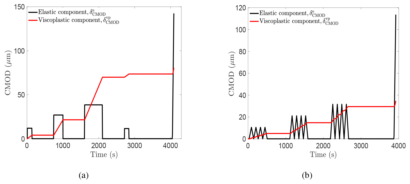
Figure 11Contribution of each individual model component to the total CMOD displacement for (a) RP16 and (b) RP17.
In this study, Schapery's constitutive model is tested for the first time for freshwater ice. The match between the model and the measured data, especially for the cyclic-recovery tests, provides a firm support of the ability of Schapery's constitutive model to describe the time-dependent response of columnar freshwater S2 ice up to crack growth initiation. Figure 11a and b show the contribution of each individual model component, elastic and viscoplastic, to the total CMOD displacement, for RP16 and RP17, respectively. As mentioned earlier, the elastic and viscoplastic components account for the total deformation. For RP16, the viscoplastic component dominated over the elastic component. For RP17, the elastic and viscoplastic components contributed equally to the total displacement.
The applicability of the proposed model and the fitted parameters is limited to the studied ice type, geometry, specimen size, ice temperature, and the current testing conditions. Variation in the operating conditions will change the dominant deformation mechanisms and the ice behavior; and accordingly, new model parameters are needed to adapt to the new response.
Interestingly, the ice behavior in the current study differs from previous experimental creep and cyclic work on freshwater ice. A large delayed elastic or recoverable component has been previously observed. Several researchers performed creep experiments on granular freshwater ice at lower temperatures (Mellor and Cole, 1981, 1982, 1983; Cole, 1990; Duval et al., 1991) and reported considerable recovery. Duval conducted torsion creep tests on glacier ice at a similar testing temperature of −1.5 ∘C (Duval, 1978). When unloaded, the ice exhibited creep recovery. According to his analysis, during loading, the internal stresses opposing the dislocation motion increase; upon unloading, the movement of dislocations produced the reversible deformation and is caused by the relaxation of internal stresses. Sinha (1978, 1979) studied columnar-grained freshwater ice and concluded that the high-temperature creep is associated with grain boundary sliding. Cole developed a physically based constitutive model in terms of dislocation mechanics (Cole, 1995) and quantified two mechanisms of anelasticity: dislocation and grain boundary relaxations. He demonstrated that the increased temperature sensitivity of the creep properties of ice within a few degrees of the melting point is due to a thermally induced increase in the dislocation density (Cole, 2020). The question then arises as to why warm columnar freshwater ice tested here showed no significant delayed elastic effect and why the microstructural changes were mainly irreversible upon unloading.
The measured ice response is a novel result for any type of ice. It is important to emphasize that in comparison with earlier freshwater ice studies, the tested samples are very warm and large. Viscoelasticity normally happens due to the elastically accommodated grain boundary sliding. Upon loading, internal stresses build up at local stress concentrations in the grain boundary geometry (triple points and grain boundary ledges). Assuming there is no microcracking, the growing stress impedes further grain boundary sliding and causes sliding in the reverse direction, giving rise to the recoverable component after unloading. However, in the present case, the measurements showed that the grain boundary sliding produced permanent deformation. Several reasons can be discussed, related to the ice temperature, microstructure, and nonlinear mechanisms in the process zone.
Concerning the effect of temperature: the warmer the temperature, the more liquid on the grain boundary. The high homologous test temperature (top ice surface ∘C) causes liquidity on the gain boundaries (Dash et al., 2006). The intergranular melt phase on the grain boundary renders the ice as a two-phase polycrystal and significantly influences the creep and recovery response. In fact, the grain boundary sliding then consists theoretically of two processes: (1) the sliding of grains over one another and (2) the squeezing in/out of the liquid between adjacent grains (Muto and Sakai, 1998). The shear behavior of the liquid film is a function of its properties (thickness and amount). The presence of this liquid at the triple points and the boundary acted as a resisting obstacle for the grains to shear and deform back to their original form, causing the viscoplastic deformation.
The microstructure (grain size, crystalline texture) could be another contributing factor. Sinha (1979) developed a nonlinear viscoelastic model, incorporating the grain size effect, to describe the high-temperature creep of polycrystalline materials. He concluded that delayed elastic strain exhibits an inverse proportionality with grain size. This suggests that the grain size (3–10 mm, Fig. 2b) of the ice samples is coarse enough not to produce any measurable viscoelastic deformation under the testing conditions. It is also probable that for this grain size, there were not enough local concentration points to arrest the grain boundary sliding and drive the recoverable and reverse sliding. In addition, Gasdaska (1994) discussed that regularly ordered and packed microstructures limit the amount of sliding and rearrangement and lead to less anelastic strain. The ice growth in the Aalto Ice Tank was very controlled and resulted in homogeneous ice sheet.
Knauss presented a thorough review of the time-dependent fracture models available to date (Knauss, 2015). The essence of the models is based on modeling the behavior in a finite cohesive/process zone which is attached to the traction-free crack tip. The one-parameter fracture mechanics encompassed by the apparent fracture toughness is not applicable (Dempsey et al., 2018). It is believed that the mechanisms taking place in the process zone play an influencing role in the current tests. The nonlinearity in the fracture zone relieved the internal stresses that would ordinarily accommodate the grain boundary sliding and generate some viscoelastic deformation upon unloading. Thus, any microstructural damage that occurred during loading manifested as permanent deformation at the end of the test.
It is noteworthy that the earlier studies used test sizes which are smaller than the plate size used here. It was shown in the DC fracture tests (Gharamti et al., 2021) that scale had an effect at the tested loading rates. It is probable that the specimen size influenced the time-dependent deformation of freshwater ice. The current tests suggest that for the large sample size and the kind of ice studied (very warm freshwater ice) under the loading applied, viscoelasticity is not an important deformation component. The experimental results support this prediction, but more tests are needed to make more general conclusions.
All the abovementioned factors might have contributed to the measured elastic–viscoplastic response. However, the question as to which factor influenced mostly the behavior is an important research question that requires more testing programs. Testing the effect of each factor separately requires a set of experiments that considers this factor while keeping all the other conditions fixed.
In the present work, five 3 m×6 m warm freshwater S2 ice specimens were tested under creep/cyclic-recovery sequences followed by a monotonic ramp. The temperature at the top surface was about −0.3 ∘C. The tests were load controlled and led to complete fracture of the specimen. The purpose of this study was to examine the time-dependent behavior of freshwater ice using a joint experimental-modeling approach.
In the experimental part, the tests aimed to (1) measure and examine the time-dependent response of columnar freshwater S2 ice through the applied creep/cyclic-recovery sequences and (2) investigate the effect of creep and cyclic sequences on the fracture parameters/behavior through the fracture monotonic ramp. The current tests were compared with other monotonically loaded tests of the same ice. The results showed that the creep and cyclic sequences had no clear effect on the failure load and the crack opening displacements at crack growth initiation. The ice response at the testing conditions was overall elastic–viscoplastic. The loading phases displayed an instantaneous transformation from the primary (transient) stage to the steady-state regime, which resulted in permanent (unrecoverable) displacement. The conducted experiments provided a novel observation for the time-dependent behavior of freshwater ice. Though the delayed elastic component has been reported as a major creep component in freshwater ice, no significant viscoelasticity was detected in this study. Several factors were discussed as possibly contributing to the observed behavior: the very warm columnar freshwater ice, liquidity on the grain boundary, large sample size, coarse grain size, and nonlinear mechanisms in the fracture zone. Testing the effect of each factor on the ice response requires a different set of experiments that varies this factor only while keeping the other conditions fixed.
In the modeling part, Schapery's nonlinear constitutive model was applied for the displacement response at the crack mouth. The elastic–viscoplastic formulation succeeded in predicting the experimental response of columnar freshwater S2 ice over the applied loading profile up to crack growth initiation. The model parameters were obtained via an optimization procedure using the N-M method by comparing the model and experimental CMOD values.
The proposed model parameters are valid only for the studied ice type, geometry, specimen size, ice temperature, and the range of applied load experienced in the experiments. Schapery's model was selected in this study, as it is able to capture the sort of time-dependent behavior known to occur in ice and produces a simple and expedient way to help understand the observed behavior. More thorough analysis with a physically based approach is left to the future.
The code used for material modeling is written in MATLAB. Scripts used for analysis and more detailed information of the experimental results are available from the authors upon request.
All authors designed the study and performed the experiments. IEG generated the results and drafted the paper. All authors commented on the text.
The authors declare that they have no conflict of interest.
The authors would like to thank David Cole for taking the time and effort to review the manuscript. The first author (Iman E. Gharamti) is thankful to Kari Santaoja for useful and enlightening discussions. The first author also thanks Murtaza Hazara for his helpful numerical advice. The second author (John P. Dempsey) thanks Business Finland for support by the Finland Distinguished Professor Programme (FiDiPro) professorship from Aalto University, as well as the sabbatical support from Aalto University, which collectively supported an annual visit in 2015–2016 and summer visits in 2017–2019.
This research has been supported by the Business Finland and the industrial partners Aker Arctic Technology, Arctech Helsinki Shipyard, Arctia Shipping, ABB Marine, Finnish Transport Agency, Suomen Hyötytuuli Oy, and Ponvia Oy (FiDiPro “Scaling of Ice Strength: Measurements and Modeling” and the ARAJÄÄ research project).
This paper was edited by Jürg Schweizer and reviewed by two anonymous referees.
Abdel-Tawab, K. and Rodin, G. J.: Analysis of primary creep of S2 fresh-water and saline ice, Cold Reg. Sci. Technol., 26, 83–96, 1997. a, b, c
Adamson, R. M. and Dempsey, J. P.: Field-scale in-situ compliance of arctic first-year sea ice, J. Cold Reg. Eng., 12, 52–63, 1998. a, b, c, d, e
Ashby, M. F. and Duval, P.: The creep of polycrystalline ice, Cold Reg. Sci. Technol., 11, 285–300, 1985. a
Ashton, G. D.: River and lake ice engineering, Water Resources Publication, Littletown, Colorado, 1986. a
Cole, D.: On the physical basis for the creep of ice: the high temperature regime, J. Glaciol., 66, 401–414, 2020. a
Cole, D. M.: Reversed direct-stress testing of ice: Initial experimental results and analysis, Cold Reg. Sci. Technol., 18, 303–321, 1990. a, b, c
Cole, D. M.: A model for the anelastic straining of saline ice subjected to cyclic loading, Philos. Mag. A, 72, 231–248, 1995. a
Dash, J., Rempel, A., and Wettlaufer, J.: The physics of premelted ice and its geophysical consequences, Rev. Modern Phys., 78, 695–741, 2006. a
Dempsey, J. P., Cole, D. M., and Wang, S.: Tensile fracture of a single crack in first-year sea ice, Philos. T. Roy. Soc. A, 376, 20170346, https://doi.org/10.1098/rsta.2017.0346, 2018. a
Duval, P.: Anelastic behaviour of polycrystalline ice, J. Glaciol., 21, 621–628, 1978. a
Duval, P., Kalifa, P., and Meyssonnier, J.: Creep constitutive equations for polycrystalline ice and effect of microcracking, in: International Union on Theoretical and Applied Mechanics (IUTAM), Springer, Berlin, Heidelberg, 55–67, 1991. a, b
Flügge, W.: Viscoelasticity, Springer-Verlag, Berlin, 1975. a
Gasdaska, C. J.: Tensile creep in an in situ reinforced silicon nitride, J. Am. Ceram. Soc., 77, 2408–2418, 1994. a
Gharamti, I. E., Dempsey, J. P., Polojärvi, A., and Tuhkuri, J.: Fracture of S2 columnar freshwater ice: size and rate effects, Acta Mater., 202, 22–34, 2021. a, b, c, d, e, f, g, h, i, j
Iliescu, D. and Schulson, E.: Brittle compressive failure of ice: monotonic versus cyclic loading, Acta Mater., 50, 2163–2172, 2002. a
Iliescu, D., Murdza, A., Schulson, E. M., and Renshaw, C. E.: Strengthening ice through cyclic loading, J. Glaciol., 63, 663–669, 2017. a
Jellinek, H. and Brill, R.: Viscoelastic properties of ice, J. Appl. Phys., 27, 1198–1209, 1956. a
Jorgen, V. G. and Picu, B. C.: Effect of step-loading history and related grain-boundary fatigue in freshwater columnar ice in the brittle deformation regime, Philos. Mag. Lett., 77, 241–247, 1998. a
Knauss, W. G.: A review of fracture in viscoelastic materials, Int. J. Fracture, 196, 99–146, 2015. a
LeClair, E. S., Schapery, R. A., and Dempsey, J. P.: Tensile creep of saline ice, in: Symposium on Inelasticity and Damage in Solids Subject to Microstructural Change, St. John's, Newfoundland, Canada, 143–153, 1996. a, b
LeClair, E. S., Schapery, R. A., and Dempsey, J. P.: A broad-spectrum constitutive modeling technique applied to saline ice, Int. J. Fracture, 97, 209–226, 1999. a, b, c, d
Le Gac, H. and Duval, P.: Constitutive relations for the non elastic deformation of polycrystalline ice, in: Physics and Mechanics of Ice, Springer, Berlin, Heidelberg, 51–59, 1980. a, b
Lou, Y. C. and Schapery, R. A.: Viscoelastic characterization of a nonlinear fiber-reinforced plastic, J. Compos. Mater., 5, 208–234, 1971. a
Mellor, M. and Cole, D.: Cyclic loading and fatigue in ice, Cold Reg. Sci. Technol., 4, 41–53, 1981. a
Mellor, M. and Cole, D. M.: Deformation and failure of ice under constant stress or constant strain-rate, Cold Reg. Sci. Technol., 5, 201–219, 1982. a
Mellor, M. and Cole, D. M.: Stress/strain/time relations for ice under uniaxial compression, Cold Reg. Sci. Technol., 6, 207–230, 1983. a, b
Michel, B.: A mechanical model of creep of polycrystalline ice, Can. Geotech. J., 15, 155–170, 1978. a
Murdza, A., Schulson, E. M., and Renshaw, C. E.: Strengthening of columnar-grained freshwater ice through cyclic flexural loading, J. Glaciol., 66, 556–566, 2020. a
Muto, H. and Sakai, M.: Grain-Boundary Sliding and Grain Interlocking in the Creep Deformation of Two-Phase Ceramics, J. Am. Ceram. Soc., 81, 1611–1621, 1998. a
Nelder, J. A. and Mead, R.: A simplex method for function minimization, Comput. J., 7, 308–313, 1965. a
Papanicolaou, G., Zaoutsos, S., and Cardon, A.: Further development of a data reduction method for the nonlinear viscoelastic characterization of FRPs, Composites Part A, 30, 839–848, 1999. a
Rist, M., Sammonds, P., Murrell, S., Meredith, P., Oerter, H., and Doake, C.: Experimental fracture and mechanical properties of Antarctic ice: preliminary results, Ann. Glaciol., 23, 284–292, 1996. a
Santaoja, K.: Mathematical modelling of deformation mechanisms in ice, PhD Thesis, Technical Research Center of Finland, Espoo, 1990. a
Schapery, R.: Thermoviscoelastic constitutive equations for polycrystalline ice, J. Cold Reg. Eng., 11, 146–157, 1997. a, b, c
Schapery, R. A.: On the characterization of nonlinear viscoelastic materials, Polym. Eng. Sci., 9, 295–310, 1969. a, b, c, d, e, f
Sinha, N. K.: Rheology of columnar-grained ice, Exp. Mech., 18, 464–470, 1978. a, b, c, d
Sinha, N. K.: Grain boundary sliding in polycrystalline materials, Philos. Mag. A, 40, 825–842, 1979. a, b
Sunder, S. S. and Wu, M. S.: A differential flow model for polycrystalline ice, Cold Reg. Sci. Technol., 16, 45–62, 1989. a, b
Sunder, S. S. and Wu, M. S.: On the constitutive modeling of transient creep in polycrystalline ice, Cold Reg. Sci. Technol., 18, 267–294, 1990. a, b
- Abstract
- Introduction
- Creep-recovery fracture experiments
- Nonlinear time-dependent modeling of S2 columnar freshwater ice
- Experimental and modeling results
- Discussion
- Conclusions
- Code and data availability
- Author contributions
- Competing interests
- Acknowledgements
- Financial support
- Review statement
- References