the Creative Commons Attribution 4.0 License.
the Creative Commons Attribution 4.0 License.
A confined–unconfined aquifer model for subglacial hydrology and its application to the Northeast Greenland Ice Stream
Thomas Kleiner
Vadym Aizinger
Martin Rückamp
Angelika Humbert
Subglacial hydrology plays an important role in ice sheet dynamics as it determines the sliding velocity. It also drives freshwater into the ocean, leading to undercutting of calving fronts by plumes. Modeling subglacial water has been a challenge for decades. Only recently have new approaches been developed such as representing subglacial channels and thin water sheets by separate layers of variable hydraulic conductivity. We extend this concept by modeling a confined–unconfined aquifer system (CUAS) in a single layer of an equivalent porous medium (EPM). The advantage of this formulation is that it prevents unphysical values of pressure at reasonable computational cost. We performed sensitivity tests to investigate the effect of different model parameters. The strongest influence of model parameters was detected in terms of governing the opening and closure of the system. Furthermore, we applied the model to the Northeast Greenland Ice Stream, where an efficient system independent of seasonal input was identified about 500 km downstream from the ice divide. Using the effective pressure from the hydrology model, the Ice Sheet System Model (ISSM) showed considerable improvements in modeled velocities in the coastal region.
- Article
(2864 KB) - Full-text XML
- BibTeX
- EndNote
Subglacial water has been identified as a key component in glacial processes; it is fundamental in driving large ice flow variations over short time periods. Recent studies have shown considerable progress in modeling these subglacial networks and coupling them to ice models. Water pressure strongly influences basal sliding and can therefore be considered a fundamental control on ice velocity and ice sheet dynamics (Gimbert et al., 2016; Lliboutry, 1968; Röthlisberger, 1972).
Generally, two fundamentally different types of drainage are identified: discrete channel and conduit systems and distributed water sheets or thin films. Distributed flow mechanisms are, for example, linked cavities (Lliboutry, 1968), flows through sediment (Hubbard et al., 1995), or thin water sheets (Weertman, 1957); they are considered inefficient and slow. Channels (Nye, 1976; Röthlisberger, 1969; Shreve, 1972) are seen as discrete single features or arborescent networks. They usually develop over the summer season when a lot of meltwater is available. It is assumed that these channelized or efficient drainage systems (able to drain large amounts of water in short time spans) are predominant in alpine glaciers and on the margins of Greenland, where substantial amounts of surface meltwater are capable of reaching the bed (van den Broeke et al., 2017). In the interior of Greenland and also in most parts of Antarctica, the water supply is limited to basal melt – a circumstance favoring distributed systems.
Seasonal variations of ice velocity have been observed and attributed to the evolution of the drainage system switching between an efficient and inefficient state in summer and winter (Bartholomew et al., 2010). For this reason, a new generation of subglacial drainage models has been developed that is capable of coupling the two regimes of drainage and reproducing the transition between them (Hewitt, 2013; Hewitt et al., 2012; Hoffman and Price, 2014; Schoof, 2010; Werder et al., 2013). While these models demonstrate immense progress for modeling spontaneously evolving channel networks, it is still a challenge to apply them on a continental scale. A comprehensive overview of the various operational and newly emerging glaciological hydrology models is given in Flowers (2015).
Distributed or sheet structures can naturally be well represented using a continuum approach, while channels usually require a secondary framework, where each feature is described explicitly. Water transport in channels is a complex mechanism that depends on the balance of melt and ice creep (Nye, 1976; Röthlisberger, 1969), channel geometry, and network topology. Additionally, the network evolves over time, which further complicates modeling of this process. When simulating channel networks, particular care must also be taken to prevent the emergence of instabilities due to runaway merging of channels (see the discussion in Schoof et al., 2012). This leads to increased modeling complexity and high computational costs. An exception to this is the work of de Fleurian et al. (2014), in which a sediment layer is used to model the inefficient drainage system and an equivalent porous layer (EPL) represents the efficient drainage of the channel network, both represented by Darcy flow through separate porous media layers. The layer representing the channels has its parameters (namely the hydraulic conductivity and the storage) adjusted to exhibit the behavior of an effective system.
We take this idea even further and apply Darcy flow to only a single layer of an equivalent porous medium (EPM), accounting for both drainage mechanisms (efficient and inefficient) by locally adjusting the effective hydraulic transmissivity. This means that we approximate the channel flow as a fast diffusion process similarly to work in de Fleurian et al. (2014). Evolution equations based on the development of channels and cavities locally adapt the transmissivity, such that high-transmissivity areas represent the efficient system, while the transmissivity is low for inefficient drainage areas. Similar approaches are known to have been applied to the modeling of fracture networks in rock (Van Siclen, 2002). This reduced complexity model does not capture channels individually but represents their effect by changing specific local properties. We prefer to use the term “equivalent porous medium” instead of “equivalent porous layer” hereafter to avoid confusion with the terminology in de Fleurian et al. (2014), although both names represent the same approach and are widely used in hydrology. Since our model aims to simultaneously represent the main properties of both drainage mechanisms (efficient and inefficient), special care must be taken when choosing the model parameters and relating them to the physical properties of a specific scenario. In particular, the geometrical and physical parameters used in this model are not directly comparable to observed quantities, but instead describe an idealized representation that gives the best fit to the available data. While this strategy may not help to advance the precise understanding of channel formation processes, it captures the overall behavior, is computationally efficient, and allows us to examine the complex interactions on larger spatial and temporal scales.
In addition, we differentiate between confined and unconfined flow in the aquifer based on the scheme presented in Ehlig and Halepaska (1976). We therefore name our new subglacial hydrology model CUAS (confined–unconfined aquifer scheme). A sketch with the geometric quantities used in CUAS and the model concept is shown in Fig. 1. While the assumption of always saturated – and therefore confined – aquifers may be true for glaciers with large water supply, it does not hold in areas with lower water input. Especially in locations far from the coast, the water supplies are often insufficient to completely fill the aquifer. Ignoring this leads to significant errors in the computed hydraulic potential and unphysical, i.e., negative, water pressure. This problem has been analyzed in detail by Schoof et al. (2012), but here we study the effect in the context of equivalent media models using unconfined flow as a possible solution.
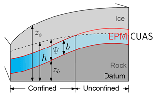
Figure 1Sketch of the EPM model and artificial geometry for experiments. The left side is towards the glacier snout. The red border shows the location of the equivalent porous medium that is modeled. The blue gradient indicates the locally increased transmissivity. When Ψ<b, the system becomes unconfined.
Large-scale ice flow models often compute the basal velocity using a Weertman-type sliding law, whereby the inverse of the effective pressure (difference between the ice overburden pressure and the water pressure) determines the velocity at the base. Low effective pressure leads to high basal velocity. Without subglacial hydrology models, the ice models simply take the ice overburden pressure as effective pressure completely neglecting water pressure or absorb all types of pressure into the sliding coefficient for the friction law without explicitly accounting for the contribution of water pressure. This is a major reason why these models struggle to represent fast-flowing areas such as ice streams. The effective pressure computed by our model can be easily coupled to an ice sheet model to improve results for fast-flowing areas.
Our work is structured as follows. In the next section, we present the one-layer equivalent porous medium model of the subglacial hydrology. In Sect. 3 the model is applied to artificial scenarios, and the sensitivity to model parameters and stability is investigated. In addition, results for seasonal forcing are presented there, and we show how the model evolves over time. Section 4 demonstrates the first application of the proposed methodology to the Northeast Greenland Ice Stream (NEGIS). The ice stream penetrates far into the Greenland mainland with its onset close to the ice divide, so sliding apparently plays a major role in its dynamics. A short conclusions and outlook section wraps up the present study.
As described above, we chose not to model the efficient and inefficient drainage systems separately, but we use a unified formulation that encompasses both types of water transport in one layer. Our model is based on the assumption that the main characteristics of subglacial hydrology can be captured by an equivalent porous media approach similar to groundwater flow in karstified aquifers (Teutsch and Sauter, 1991). Thus, a Darcy-type groundwater flow equation can be used. This does not mean that we expect the water transport to be through the subglacial sediments, but rather through an equivalent porous medium, which also accounts for cavities and channels. An appropriate adjustment of its properties can make them capable of exhibiting the same effective transmissivity as, e.g., channel systems. The model does not represent water flow through individual channels (which would be represented by Darcy–Weisbach). Instead, we approximate fast flow through the efficient system by Darcy flow with increased transmissivity. We derive the temporal evolution of the controlling parameter – effective transmissivity – from the temporal evolution of the volume occupied by channels (de Fleurian et al., 2016) and cavities (Werder et al., 2013).
The vertically integrated continuity equation in combination with Darcy's law leads to the general groundwater flow equation (see, e.g., Kolditz et al., 2015):
where h is the hydraulic head (water pressure in terms of water surface elevation above an arbitrary datum also known as the piezometric head), S is the storage coefficient (change in the volume of stored water per unit change of the hydraulic head over a unit area), T is the transmissivity, and Q is the source term. For a confined aquifer, T=Kb, where K is the hydraulic conductivity and b is the equivalent porous medium thickness. S=Ssb with specific storage Ss given by
where the acceleration is due to gravity g, porosity ω and compressibility α are the material parameters for the porous medium, and ρw and βw are the water density and water compressibility, respectively.
Water pressure Pw and effective pressure N are related to the hydraulic head as
and
where is the local height of the head over bedrock zb and Pi=ρigH is the cryostatic ice overburden pressure exerted by ice with thickness H and density ρi (see Fig. 1).
2.1 Opening and closure
Opening and closure of channels are governed by the melt at the walls due to the dissipation of heat and the pressure difference between the inside and outside of the channel leading to creep deformation. Linked cavities open due to sliding over bedrock bumps (Kamb, 1987; Walder, 1986). Most existing models use separate descriptions for the efficient and the inefficient transport system (e.g., continuum description for sheet-flow and discrete channels), leading to two sets of equations that need to be coupled. Our single-layer medium allows us to use a single set of equations that includes melt opening, cavity opening, and creep closure, which is quite compelling given that channels and sheets are only the extremes of a much more varied drainage system. In this regard, our model is similar to the one by Schoof (2010), though we use a continuum description, which can cause instabilities (runaway growth) when the melt rate is much larger than the creep closure (Hewitt, 2011). However, the diffusive nature of our model avoids this problem by distributing the growth over a small area, thus preventing infinite growth and leading to a stable configuration.
We adopt the classical channel equations from Nye (1976) and Röthlisberger (1972) as in de Fleurian et al. (2016) and cavity opening (Kamb, 1987; Walder, 1986) as in Werder et al. (2013) to evolve the effective transmissivity. The details on this are shown in Appendix A. Thus
where L is the latent heat, β is a factor governing opening via sliding over bedrock protrusions, vb is the basal velocity of the ice, A is the creep rate factor depending on temperature, and n is the creep exponent, which we choose to be n=3. The dimensionless parameter depends on the height br and distance Lr of the bedrock protrusions. The cavity opening formulation does not yet include a limit imposed by the bump height. Depending on the sign of N, creep closure as well as creep opening can occur. Negative effective pressure over a prolonged time is usually considered unphysical, and the correct solution for this would be to allow the ice to separate from the bed (see, e.g., Schoof et al., 2012 for a possible solution). However, in the context of our equivalent layer model, the creep term in Eq. (5) is still applicable because this is how a channel would behave for N<0. In Sect. 3.1, we test the sensitivity of T and N to the magnitudes of K, β, and A.
2.2 Confined–unconfined aquifer scheme
The water balance equation (Eq. 1) and the pressure equation (Eq. 3) assume that the porous medium is always completely filled with water. As this is not always true, especially for areas with significant bedrock topography combined with low water input, it is possible to obtain unphysical negative water pressures with this method. A possible solution is to relax the assumption of a medium that is always filled and consider the general form (confined–unconfined). We follow Ehlig and Halepaska (1976) and write the general form for the confined–unconfined problem:
Now the effective transmissivity Te and the effective storage coefficient Se depend on the head and are defined as
and
where
This means that as soon as the head sinks below the aquifer height, the system becomes unconfined, and therefore only the saturated section contributes to the transmissivity calculation. This also prevents the head from falling below the bedrock as detailed in Sect. 3.2. Additionally, the mechanism for water storage changes from elastic relaxation of the aquifer (confined) to dewatering under the forces of gravity (unconfined). The amount of water released from dewatering is described by the specific yield Sy. Since this amount is usually orders of magnitudes larger than the release from the confined aquifer (Sy≫Ssb), it is useful to introduce a gradual transition as in Eq. (9), controlled by a user-defined transition parameter d.
At each time step, the model solves the equation for the hydraulic head (Eq. 6) and evolves the transmissivity of the EPM according to Eq. (5).
Note that the transmissivity is not homogeneous, making Eq. (6) nonlinear. This fits with our approach to describe the effective system (channels) by locally increasing the transmissivity. The drawback of this formulation is that the evolution of T does not affect areas where the flow is unconfined (as Te=KΨ for unconfined). Also, the melt rate for the opening term (Eq. 5) does not account for the possibility of unconfined flow. This is not an issue because unconfined flow only occurs in the locations where the water supply is low, i.e., where no channels are expected to develop. Details on the numerical implementation can be found in Appendix B. The benefit of this approach is discussed in Sect. 3.2.
Testing the EPM concept and determining parameters is not straightforward because there are no directly comparable physical properties. Moreover, observations and measurements of subglacial processes are in general difficult to obtain and sparse. We address this by testing the model with some of the benchmark experiments of the Subglacial Hydrology Model Inter-comparison Project (SHMIP; de Fleurian et al., 2018). The proposed artificial geometry mimics a land-terminating ice sheet margin measuring 100 km in the x direction and 20 km in the y direction. The bedrock is flat ( m), with the terminus located at x=0 km, while the surface zs is defined by a square root function: . Here, we use the SHMIP/B2 setup, which includes 10 moulins with steady supply. Boundary conditions are set to zero influx at the interior boundaries (y=0 km, y=20 km, x=100 km) and zero effective pressure at the terminus. All experiments start with the initial conditions that imply zero effective pressure and are run for 50 years to ensure that a steady state is reached.
3.1 Parameter estimation and sensitivity
SHMIP is primarily intended as a qualitative comparison between different subglacial hydrology models, where results from the GlaDS model (Werder et al., 2013) serve as common ground. Here, we use it as a basis for an initial tuning and a study of the sensitivity of our model with regard to parameters. SHMIP presents an in-depth comparison of all models, which is also the reason why we do not show a comparison to other models in this study.
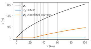
Figure 2Experiments with artificial geometries. Vertical lines denote moulin positions for SHMIP/B2. The orange line shows the modified bedrock used to illustrate the impact of the confined–unconfined scheme as discussed in Sect. 3.2
Table 1Physical constants used in the model. We distinguish between well known (upper half) and estimated or uncertain (lower half) parameters.
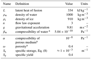
a Values from de Fleurian et al. (2014).
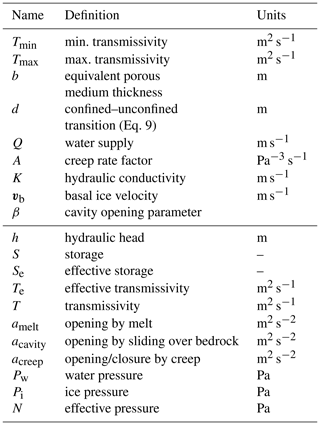
In Table 1, we show the physical constants used in all setups and runs. The values in the lower half are properties of the porous medium and are only estimated. Since they are utilized in the context of the EPM concept, this is not an issue. Table 2 contains the model parameters in the upper part and the variables computed by the model in the lower part.
We divide the sensitivity analysis into a general block investigating the sensitivity to the amount of water input into moulins, the layer thickness b, the confined–unconfined transition parameter d, and the grid resolution dx (Fig. 3) and a block that examines the parameters directly affecting channel evolution such as the creep rate factor A, conductivity K, and the bounds for the allowed transmissivity Tmin and Tmax (Fig. 4). In Table 3, we present values that lead to the best agreement with the SHMIP benchmark experiments and thus which are used in the following as the baseline for our sensitivity tests.
Table 3Selected baseline parameters for all experiments unless otherwise noted. These parameters best match the SHMIP targets.
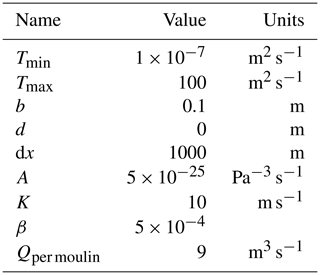
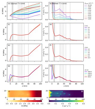
Figure 3Results from the general sensitivity experiments showing the dependence of N (left) and T (right) on (a–b) the water supply from moulins Qmoulin (results for deactivated transmissivity evolution are shown by dashed lines), (c–d) the aquifer layer thickness b, (e–f) the confined–unconfined transition parameter d, and (g–h) the grid resolution dx. Values shown are averaged along the y axis to represent cross-sections at flow lines. Transmissivity plots are cut off at 0.5 m2 s−1 to improve visibility of the relevant range. Panels (i) and (j) show the two-dimensional distributions (map view) of the results using the best-fit baseline parameters.
In Fig. 3a and b, the model's reaction to different amounts of water input through the moulins is shown. With deactivated transmissivity evolution (, dashed lines), larger water inputs lead to higher water pressure and hence lower effective pressure N. In this case, a moulin input of 18 m3 s−1 leads to negative values of N. With activated evolution of T, the transmissivity adapts to the water input: as more water enters the system through moulins, the transmissivity rises. Vertical gray bars show the location of moulins along the x axis, and the most significant increase in T occurs directly downstream of a moulin. This happens because the water is transported in this direction, leading to increased melt. At the glacier snout (x=0), the ice thickness is at its lowest so almost no creep closure takes place; hence, the transmissivity grows large for all tested parameter combinations. Significant development of effective drainage is visible for inputs above 0.07 m3 s−1 (yellow line). The resulting effective pressure decreases with rising water input as the system becomes more efficient at removing water. Up to ca. 35 km distance from the snout, this results in similar values of N for all forcings above 0.28 m3 s−1. The system adapts so that it can remove all of the additional water efficiently. In Fig. 3i and j, the two-dimensional distributions of N and T are shown for the baseline parameters. In the following, we denote regions of high transmissivity as channels, even though our model does not directly simulate them. Those channels form downstream from moulins and continue straight towards the ocean. The effective pressure drops around water inputs and along the channels.
We observe no sensitivity of our result to the layer thickness b (Fig. 3c and d). Because we use transmissivity, b does not influence the flow of water directly, but is important to decide when the system becomes unconfined, as well as to determine the storage (see Eq. 8). However, in this experiment the system has sufficient water input so that all cells are confined in the steady state and also the storage has no influence on the long-term solution. (The storage determines how fast a pressure change travels through the system, but is irrelevant for the steady state.)
The large availability of water also explains why the confined–unconfined transition parameter d does not show noticeable effects on the results (Fig. 3e and f) – the system is always confined.
Grid resolution dx has little influence on the pressure distribution and a minor effect on the transmissivity downstream (Fig. 3g and h). However, coarse resolutions are unable to resolve the steps that appear at the moulins.
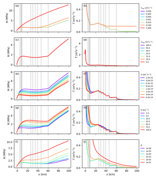
Figure 4Results from parameters directly related to opening and closure: limits on the transmissivity Tmin (a, b) and Tmax (c, d), creep rate factor A (e, f), conductivity K (g, h), and cavity opening parameter β (i, j). Values shown are averaged along the y axis to represent cross-sections at flow lines. Transmissivity plots are cut off at 0.5 m2 s−1 to improve visibility of the relevant range.
In Fig. 4a and b, we show the results for different values of Tmin. Tmin acts as a numerical limit to avoid infinite growth for ill-posed conditions and generally does not show influence on the results. If Tmin is chosen to be very large (0.1 m2 s−1 or larger), this dominates the balance between opening and closure and leads to high water flux, increasing the effective pressure.
Tmax (Fig. 4b and c) has no visible impact on the resulting pressure distribution.
The creep rate factor A determines the “softness” of the ice and therefore affects the creep term in Eq. (5). Larger values of A imply warmer ice and hence more creep closure (see Fig. 4e and f). Note that this also affects creep opening for N<0.
The conductivity K describes the flux of water through the system and therefore determines the melt term (see Eq. 5). Larger values of K lead to higher transmissivity and more water transport, resulting in lower Pw and higher N.
In order to explore the solution dependence on cavity evolution, we assume the basal ice velocity (as in SHMIP) and vary β. β parametrizes the bedrock geometry and incorporates the height and distance of protrusions. As expected, larger values of β lead to more opening and, therefore, a higher effective pressure. With values as high as , the cavity opening completely dominates the transmissivity evolution, and the effect of moulins is not visible anymore.
3.2 The benefit from treating unconfined aquifer
As described above, the confined–unconfined aquifer approach is advantageous for obtaining physically meaningful pressure distributions. In the example illustrated in Fig. 5, we use a slightly modified geometry, where the bedrock rises towards the upstream boundary, forming a slab . The supply is constant in time and space, and we choose a low value of m s−1 (≈ 2.5 mm a−1) to compare our improved scheme to the simple confined-only case. Figure 5 shows a comparison of the steady-state solutions: for the confined-only case, the hydraulic head drops below the bedrock in the upstream region. This results in negative water pressure for these regions. Addressing this by simply limiting the water pressure to zero would result in inconsistencies between the pressure field and the water supply.
Our new scheme limits the transmissivity when the head approaches the bedrock and by this means ensures Pw≥0 in a physically consistent way. Additionally, the confined-only solution completely depends on boundary conditions and supply terms; basal topography has no influence in this case (apart from governing dK∕dt). The possibility of the aquifer to become unconfined captures the expected behavior much better: at high water levels, water pressure distribution dominates water transport, while at low levels the bed topography becomes relevant.
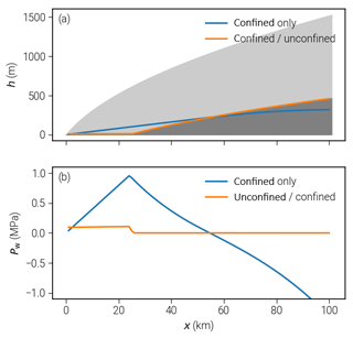
Figure 5Advantages of using the confined–unconfined aquifer scheme (CUAS): values of head and water pressure for geometries with non-flat bedrock. (a) Computed head for the confined and combined scheme with ice geometry in the background. In the confined-only case, the head goes below bedrock. (b) Resulting water pressure; only for the combined scheme is the pressure always nonnegative.
3.3 Seasonal channel evolution and properties
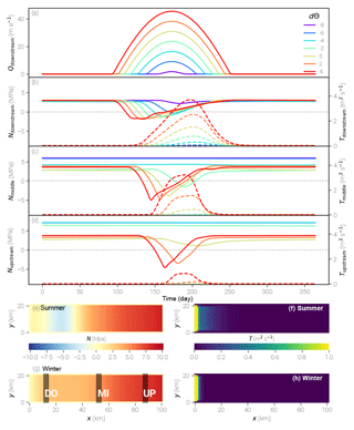
Figure 6Results for one season of the SHMIP/D experiment. In panels (b)–(d), the left axis (effective pressure) corresponds to the solid lines, while the right axis (transmissivity) specifies the values for the dashed lines. The values at the given positions (upstream, middle, downstream) are averaged over the corresponding areas indicated in panel (g). Panels (e)–(h) show two-dimensional distribution maps of d run.
In order to understand our model's ability to simulate the seasonal evolution of subglacial systems, we selected the setup SHMIP/D and ran it with different values of key model parameters. This experiment does not include any moulins but prescribes a nonuniform spatial distribution of supply instead that also varies seasonally. A simple degree day model with the varying temperature parameter dΘ provides water input rising from the downstream end (lowest elevated) of the glacier towards the higher elevated areas over summer:
Here, yr=31 536 000 s denotes the number of seconds per year, K m−1 is the lapse rate, m K−1 s−1 is the degree day factor, and m s−1 represents additional basal melt. The resulting seasonal evolution of the supply is shown in Fig. 6a. The model is run for 10 years so that a periodic evolution of the hydraulic forcing is generated. Here, we present the result for one parameter set only, since the model is not very sensitive in this setup.
We chose three different locations to present N and T during the season: downstream of the glacier close to the snout, in the center, and at a far upstream location (Fig. 6b–d; the locations are marked in panel g). The time series are spatially averaged over these locations, with solid lines representing the effective pressure and dashed lines the transmissivity. Water input increases during the summer months, while the corresponding effective pressure drops. With a time lag the transmissivity rises in response. Supply develops from the downstream end towards the upstream end of the glacier over the season, so the decline in N at the downstream location (Fig. 6b) is instantaneous when the supply rises, while at the locations further inland (Fig. 6c and d), N reacts later during the year. At the middle location, the drop in N is only visible for temperature parameters of −2 and higher. The rise in transmissivity occurs for the three highest temperatures. Finally, at the upstream position, only for dΘ=4 and dΘ=2 does the effective pressure drop below zero, while for dΘ=0 the drop is smaller in magnitude and more prolonged. The transmissivity rise is only significant for dΘ=4 at this location. While the onset and minima of the decline in N strongly depend on the amount and timing of the water input for all values of dΘ, the maximum of T and also the time when N returns to winter conditions is similar. For the downstream position, the maximum transmissivity is reached for day 210 (not visible in the figure), and N reaches its background value approximately 25 days later. At the center and upstream positions, this behavior is less pronounced but generally similar.
The observed behavior is expected and indicates that our model is able to represent the seasonal evolution of the subglacial water system. Increasing water supply over the year leads to rising water pressure and dropping effective pressure. When the transmissivity rises in response, the effective pressure goes up again despite the supply not yet falling again because the more efficient system is able to transport the water away. For the cases where no visible change in T occurs such as d (blue line in Fig. 6b), the effective pressure follows the supply at the terminus with a small delay, while at the center position (d; cyan line in Fig. 6c), the minimum is offset by the time needed for the supply to reach that location. The maximum in transmissivity T is reached later because, once the system becomes efficient, increased water transport stimulates melting that opens the system even more. This self-reinforcing process is only stopped when enough water is removed and the reduced water flux reduces the melt again. We assume that this leads to similar locations of the transmissivity maxima for different dΘ values and the resulting similar reemerging of winter conditions in N.
In this experiment, N becomes negative during the seasonal evolution, which is not physically meaningful. We attribute such behavior to a lack of adjustment of water supply to the state of the system. In reality, the supply from runoff or supraglacial drainage would cease as soon as the pressure in the subglacial water system becomes too high; here we simply continue to pump water into the subglacial system without any feedback. This then leads to negative values of N. It is also consistent with the finding that N becomes negative earlier in the season in cases of higher supply. We will address this deficiency in future work.
The role of subglacial hydrology in the genesis of ice streams is not yet well understood. NEGIS is a very distinct feature of the ice sheet dynamics in Greenland; thus, the question about the role of subglacial water in the genesis of NEGIS is critical. The characteristic increase in horizontal velocities becomes apparent about 100 km downstream from the ice divide (Vallelonga et al., 2014). Further downstream, the ice stream splits into three different branches: the 79∘ North Glacier (79NG), Zacharias Isbrae (ZI), and Storstrømmen. Thus far, large-scale ice models have only been able to capture the distinct flow pattern of NEGIS when using data assimilation techniques such as inversion for the basal friction coefficient (Goelzer et al., 2018). It is assumed that most of the surface velocity can be attributed to basal sliding amplified by basal water instead of ice deformation (Joughin et al., 2001). This means that the addition of subglacial hydrology might have the potential to improve the results considerably. While many glaciers in Greenland have regularly draining supraglacial lakes and runoff driving a seasonality of the flow velocities, little is known about the effect at NEGIS (Hill et al., 2017). Because of this lack of data, to avoid an increased complexity, and to focus on the question as to whether basal melt alone can account for the development of an efficient system, we do not include any seasonal forcing in our experiment. Our setup includes the major parts of this system. The pressure-adjusted basal temperature Θpmp obtained from the Parallel Ice Sheet Model (Aschwanden et al., 2016) is utilized to define the modeling region. We assume that for freezing conditions at the base (Tpmp<0.1 K), basal water transport is inhibited and take this as the outline of our model domain. Figure 7 shows the selected area and PISM basal melt rates used as forcing.
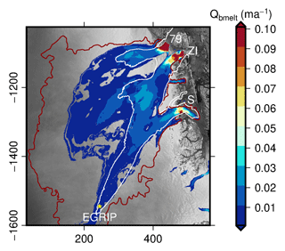
Figure 7Boundary conditions and forcing for the NEGIS experiment. The basal melt rate from PISM and the contour line for (red) used as a model boundary are shown. The white line indicates the 50 m a−1 velocity contour.
For the ice geometry, we use the bed model of Morlighem et al. (2014) interpolated on a 1.2 km grid. Boundary conditions at lateral margins are set to no flux, whereas the termini at grounding lines are defined as Dirichlet boundaries with a prescribed head that implies an effective pressure of zero. This means that the water pressure at the terminus is equal to the hydrostatic water pressure of the ocean, assuming floating conditions for the ice at the grounding line. Parameters used for this experiment are the same as in our sensitivity study (Table 3).
The simulation is run for 50 years to reach a steady state. Despite a high resolution (444×481), computing time for this setup is still reasonable (3.5 h on a single core of Intel Xeon Broadwell E5-2697).
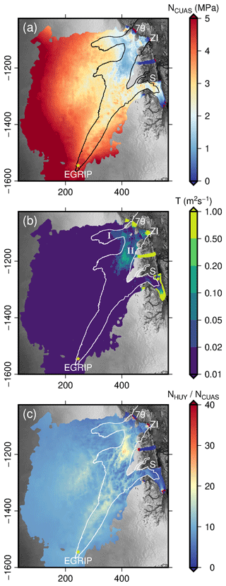
Figure 8Results for the NEGIS region with forcing due to basal melt (PISM) representing winter conditions. White lines indicate the 50 ma−1 velocity contour. Panel (a) shows the effective pressure NCUAS, panel (b) shows the transmissivity T (logarithmic scale), and panel (c) shows the quotient of the ice overburden pressure above flotation and the effective pressure computed by CUAS.
The resulting distributions of effective pressure and transmissivity are shown in Fig. 8a and b, respectively. As expected, effective pressure is highest at the ice divide and decreases towards the glacier termini. Transmissivity is low for the majority of the study area, with the exception of the vicinity of grounding lines and two distinct areas that touch in between 79NG and ZI. The northern area (marked I in Fig. 8b) is located at the northern branch of 79NG and has no direct connection to the snout. The second area (marked II in Fig. 8b) emerges in the transition zone between the southern branch of 79NG and ZI and covers an area approximately twice as large as area I with higher values of T. It reaches down to the snout of ZI.
Comparing the effective pressure distribution to the observed velocity (Rignot and Mouginot, 2012) – we chose the 50 ma−1 contour line as indicator of fast flow – we observe a high degree of overlap between the fast-flowing regions and those with low effective pressure (below 1 MPa) over most of the downstream domain of our study area. Storstrømmen shows higher effective pressure downstream than 79NG and ZI, which is in accordance with lower observed horizontal velocities for that glacier (Joughin et al., 2010). At the onset of the NEGIS, the effective pressure is high, and no relationship to the flow velocity can be observed.
To further examine the possible influence of our hydrology model to basal sliding, we investigate the impact on the sliding law. We chose to compare our computed NCUAS to the reduced ice overburden pressure defined in Huybrechts (1990) as for zb<zsl and NHUY=Pi otherwise. The quotient of NHUY to NCUAS is shown in Fig. 8c to demonstrate where the application of our hydrology model would increase basal velocities.

Figure 9Horizontal surface velocity: ISSM with reduced ice overburden pressure NHUY (a), PISM result from Aschwanden et al. (2016), interpolated to unstructured ISSM grid (b), ISSM with effective pressure from our hydrology model NCUAS (c), and observed velocities (Rignot and Mouginot, 2012) (d).
In order to demonstrate the effect of the modeled subglacial hydrology system on the NEGIS ice flow, we set up a simple, one-way coupling to an ice flow model. Here, we use the Ice Sheet System Model (Larour et al., 2012), an open source finite element flow model appropriate for continental-scale and outlet glacier applications (Bondzio et al., 2017; Morlighem et al., 2016). The modeling domain covers the grounded part of the whole NEGIS drainage basin. The ice flow is modeled by the higher order approximation (Blatter, 1995; Pattyn, 2003) in a three-dimensional model, which accounts for transversal and longitudinal stress gradients. In the HO model we do not perform a thermo-mechanical coupling, but prescribe a depth-averaged hardness factor in Glen's flow law instead. Model calculations are performed on an unstructured finite element grid with a resolution of 1 km in fast flow regions and of 20 km in the interior. Basal drag τb is determined by a Budd sliding law:
where k2 is a positive constant. We run two different scenarios, where (1) the effective pressure is parametrized as the reduced ice overburden pressure, N=NHUY, and (2) the effective pressure distribution is taken from the hydrological model at steady state, N=NCUAS. The value of k2 is tuned in order to have ice velocities of approximately 1500 m a−1 at the grounding line at the 79NG. For both scenarios, the value of k2 is 0.067 s m−1. The results for both scenarios are shown in Fig. 9a and c, respectively. Additionally, we show the observed velocities (Rignot and Mouginot, 2012) and the PISM surface velocities (Aschwanden et al., 2016). Note that the latter is a PISM model output on a regular grid interpolated to the unstructured ISSM grid.
Velocities computed with the reduced ice overburden pressure are generally too low and do not resemble the structure of the fast-flowing branches at all. The result from PISM shows distinct branches for the different glaciers, which display a relatively sharp separation from the surrounding area. Note that PISM also uses a basal hydrology model as described in Bueler and van Pelt (2015). Velocities are slightly lower than observed velocities especially for ZI and in the area where ZI and 79NG are closest. In the upper part towards the ice divide, the ice stream structure is not visible in the velocities. The ISSM using effective pressure computed by CUAS produces high velocities towards the ocean that closely resemble N. The observed sharp transition between the ice streams and the surrounding ice is poorly reproduced. While the stream structure is far too diffused, the different branches can be discerned and the velocity magnitude for the glaciers appears reasonable. The inland part is similar to observed velocities but – as in the PISM simulation – the upper part where NEGIS is initiated is not present. The onset of NEGIS is thought to be controlled by high local anomalies in the geothermal flux (Fahnestock et al., 2001), which PISM currently does not account for. Higher geothermal flux would lead to more basal melt and hence water supply in the hydrology model. However, the consequences for the modeled effective pressure would require further experiments which are not in the scope of this paper. In Table 4, we present some statistics of the results: the root mean square error (L2-norm), Pearson correlation coefficient r1, and Δv (L1-norm) between the modeled and observed velocities.
(Aschwanden et al., 2016)Table 4Comparison of modeling results for horizontal ice velocity to observed values (Rignot and Mouginot, 2012). Herein RMSE denotes the root mean square error or L2-norm, r2 is the Pearson correlation coefficient, and ΔV is the L1-norm.

We find it impressive that even without extensive tuning, we can considerably improve the velocity field in ISSM by our simple one-way coupling to the hydrology model. The results in this section are not to be understood as a thorough study of the NEGIS, but only as a first application of the model to a real geometry. A complete study requires extended observations in order to determine the optimal model parameters. However, we are confident that our results represent the general aspects of the hydrological system at NEGIS. Based on our sensitivity and seasonal experiments (Sect. 3.1 and 3.3) we expect the high-transmissivity areas to be a stable feature, which would extend or retract depending on the chosen values of the melt and creep parametrizations but not change their location. Available supply plays a more important role here, and we assume that different basal melt distributions – or the addition of surface melt – might considerably change the position and the extent of the efficient system and, therefore, the effective pressure distribution as can be seen in Sect. 3.3.
The onset of NEGIS is not reproduced in the PISM simulation as well as in our ISSM result. Since the ice is slow in the PISM results in that area, basal melt rates are low, and, since we use these as input in our hydrology model, it is expected that our model computes low water pressure here. In our opinion, this represents another point in favor of having a real two-way coupling between the ice model and the basal hydrology model in order to obtain good results. These results could then in turn be used to guide further optimization of the modeling parameters in our hydrology model in the future.
We present the first equivalent porous medium model for subglacial hydrology that includes the treatment of unconfined water flow. It only uses a single conductive layer with adaptive transmissivity. Since extensive observations of the subglacial system are rare, our approach to fit a simple parametrization of the effective Darcy model to the available data can be an advantage.
We find strong model sensitivity to grid spacing dx, the parametrization of melt amelt, creep closure acreep, and the cavity opening parameter, while the sensitivity to the limits of transmissivity and the confined–unconfined transition parameter d is low. Our model robustly reproduces the seasonal cycle with the development and decline of the effective system over the year.
In our NEGIS experiments, we find the presence of a partially efficient system for winter conditions. The distribution of effective pressure broadly agrees with observed velocities, while the upstream part is not represented correctly. When coupled to ISSM, our hydrology model notably improves computed velocities.
A number of aspects of the proposed model can be further developed; those include improved parametrizations of several physical mechanisms (e.g., adding feedback between pressure and water supplies), changing the hydraulic transmissivity coefficient to a tensor-valued one to better represent the anisotropy of channel networks, and, last but not least, the transition to a mixed formulation of the Darcy equation discretized on an unstructured mesh in order to preserve mass conservation and to improve resolution in the areas of interest.
The dataset used for the NEGIS experiment is the 1.2 km resolution result from Aschwanden et al. (2016), which can be obtained from the original authors upon request.
The channel cross-sectional area Ac expands when there is more melt than ice inflow due to creep; thus the mass change per unit length (unit: ) caused by melt () and creep () is given as (Cuffey and Paterson, 2010)
This is equivalent to
which describes the mass change per unit area (unit: ). Note that Ac is the channel volume per unit length and bc is the same channel volume, but per unit area and thus a thickness.
Nye (1976) found for the closure of channels due to creep that
where Rc denotes the channel radius (notation as in Cuffey and Paterson, 2010). A and n are the creep parameters for ice given in Tables 1 and 2. Multiplication by on both sides leads to
Rewriting the left side to area, using the chain rule () yields
thus
or again as a change per unit area:
Heat produced over the line element ds in unit time is QwG, and pressure melting point (PMP) effects are , which leads to
(Cuffey and Paterson, 2010) where represents the melt rate (mass per unit length of wall in unit time). The magnitude of gradient of the hydraulic potential is given by
Neglecting the PMP effects, we obtain
As before, we can write that as a change per unit area instead:
where is now the flux per unit length and ; this is
which can be rewritten as
Inserting from Eq. (A7) and from Eq. (A13) into Eq. (A2) and dividing by ρi results in
Note that the right-hand side of Eq. (A14) is used in de Fleurian et al. (2016) to evolve the equivalent porous layer (EPL) thickness, representing only the channels.
We assume that changes within the channel network (e.g., the increase/decrease of cross-sectional area of one, some, or many channels or just by the variation in the number of channels) can be translated into a large-scale/average change in equivalent transmissivity1. Thus, we obtain our evolution equation for the transmissivity by multiplying Eq. (A14) by the constant hydraulic conductivity coefficient K of the EPM as
The transmissivity evolution could also be applied to model situations when K is varying without any reformulation.
We also account for cavity opening due to sliding over bedrock bumps in the model using a similar notation as for the channel evolution above. Cavity opening is related to basal sliding speed vb and bump geometry through (Werder et al., 2013)
where depends on the typical height br and distance Lr of the bump. Here we use β as a model tuning parameter. Cavity opening again translates into a contribution to the transmissivity evolution and we finally obtain
We discretize the transient flow equation (Eq. 6) on an equidistant rectangular grid using a Crank–Nicolson scheme. For the sake of completeness, we give the equations for a non-equidistant grid here. For the spatial discretization, we use a second-order central difference scheme (Ferziger and Perić, 2002), leading to the spatial discretization operator for the head ℒh:
where half-grid values of T denote harmonic rather than arithmetic averages computed using Eq. (7), where
denote central, forward, and backward differences, respectively. Rewriting this more compactly in compass notation,
where
We use the Crank–Nicolson semi-implicit method for computing our hydraulic head:
(where Θ=0.5 for Crank–Nicolson) and then update the transmissivity with an explicit Euler step:
where we use a combined forward- and backward-difference scheme for the discretization of (∇h)2 in Eq. (5):
Compared to central differences, this stencil is more robust at nodes with large heads caused by moulins.
The time step is chosen sufficiently small so that the discretization error is dominated by the spatial discretization. Additionally, we check that the time step is small enough for the unconfined component of the scheme to become active by restarting the time step with a decreased Δt if at any point h<zb.
All variables are co-located on the same grid, but the transmissivity T is evaluated at the midpoints between two grid cells using the harmonic mean due to its better representation of transmissivity jumps (e.g., at no-flow boundaries).
A disadvantage of this discrete formulation is that it is not mass-conservative (see, e.g., Celia et al., 1990). The solution to this is to use a mixed formulation for Darcy flow in which also the Darcy velocity is solved for. However, in our application, the resulting error is very small, and we plan to implement the mixed formulation approach in future work.
The authors declare that they have no conflict of interest.
This work is part of the GreenRISE project, a project funded by the Leibniz-Gemeinschaft: WGL Pakt für Forschung SAW-2014-PIK-1. We kindly acknowledge the efforts of Basile de Fleurian und Mauro Werder who designed and supported the SHMIP project. We highly benefited from their well-developed test geometries and fruitful discussions, not only at splinter meetings.
Basile de Fleurian helped in the development of the method by suggesting unconfined aquifer flow as a solution for negative water pressure.
We acknowledge Andy Aschwanden for providing basal melt rates, temperatures, and
velocities simulated by PISM. Development of PISM is supported by NASA
grants NNX13AM16G, NNX16AQ40G, and NNH16ZDA001N and by NSF grants PLR-1644277 and
PLR-1603799.
The article processing charges for this open-access
publication were covered by the
Potsdam Institute
for Climate Impact Research (PIK).
Edited by: Robert Arthern
Reviewed by: Douglas Brinkerhoff and one anonymous referee
Aschwanden, A., Fahnestock, M. A., and Truffer, M.: Complex Greenland outlet glacier flow captured, Nat. Commun., 7, 10524, https://doi.org/10.1038/ncomms10524, 2016. a, b, c, d, e
Bartholomew, I., Nienow, P., Mair, D., Hubbard, A., King, M. A., and Sole, A.: Seasonal evolution of subglacial drainage and acceleration in a Greenland outlet glacier, Nat. Geosci., 3, 408–411, https://doi.org/10.1038/ngeo863, 2010. a
Blatter, H.: Velocity and stress fields in grounded glaciers: a simple algorithm for including deviatoric stress gradients, J. Glaciol., 41, 333–344, https://doi.org/10.3189/S002214300001621X, 1995. a
Bondzio, J. H., Morlighem, M., Seroussi, H., Kleiner, T., Rückamp, M., Mouginot, J., Moon, T., Larour, E. Y., and Humbert, A.: The mechanisms behind Jakobshavn Isbræ's acceleration and mass loss: A 3-D thermomechanical model study, Geophys. Res. Lett., 44, 6252–6260, https://doi.org/10.1002/2017GL073309, 2017. a
Bueler, E. and van Pelt, W.: Mass-conserving subglacial hydrology in the Parallel Ice Sheet Model version 0.6, Geosci. Model Dev., 8, 1613–1635, https://doi.org/10.5194/gmd-8-1613-2015, 2015. a
Celia, M. A., Bouloutas, E. T., and Zarba, R. L.: A general mass-conservative numerical solution for the unsaturated flow equation, Water Resour. Res., 26, 1483–1496, https://doi.org/10.1029/WR026i007p01483, 1990. a
Cuffey, K. M. and Paterson, W. S. B.: The physics of Glaciers, Elsevier, Oxford, 4th edn., 2010. a, b, c
de Fleurian, B., Gagliardini, O., Zwinger, T., Durand, G., Le Meur, E., Mair, D., and Råback, P.: A double continuum hydrological model for glacier applications, The Cryosphere, 8, 137–153, https://doi.org/10.5194/tc-8-137-2014, 2014. a, b, c, d
de Fleurian, B., Morlighem, M., Seroussi, H., Rignot, E., van den Broeke, M. R., Kuipers Munneke, P., Mouginot, J., Smeets, P. C. J. P., and Tedstone, A. J.: A modeling study of the effect of runoff variability on the effective pressure beneath Russell Glacier, West Greenland, J. Geophys. Res.-Earth, 121, 1834–1848, https://doi.org/10.1002/2016JF003842, 2016. a, b, c
de Fleurian, B., Werder, M. A., Beyer, S., Brinkerhoff, D. J., Delaney, I., Dow, C. F., Downs, J., Gagliardini, O., Hoffman, M. J., LeB Hooke, R., Seguinot, J., and Sommers, A. N.: SHMIP The subglacial hydrology model intercomparison project, J. Glaciol., 1–20, https://doi.org/10.1017/jog.2018.78, 2018. a
Ehlig, C. and Halepaska, J. C.: A numerical study of confined-unconfined aquifers including effects of delayed yield and leakage, Water Resour. Res., 12, 1175–1183, https://doi.org/10.1029/WR012i006p01175, 1976. a, b
Fahnestock, M., Abdalati, W., Joughin, I., Brozena, J., and Gogineni, P.: High geothermal heat flow, basal melt, and the origin of rapid ice flow in central Greenland, Science, 294, 2338–2342, https://doi.org/10.1126/science.1065370, 2001. a
Ferziger, J. H. and Perić, M.: Computational Methods for Fluid Dynamics, Springer-Verlag Berlin Heidelberg, 3rd edn., https://doi.org/10.1007/978-3-642-56026-2, 2002. a
Flowers, G. E.: Modelling water flow under glaciers and ice sheets, P. R. Soc. A, 471, 20140907, https://doi.org/10.1098/rspa.2014.0907, 2015. a
Gimbert, F., Tsai, V. C., Amundson, J. M., Bartholomaus, T. C., and Walter, J. I.: Subseasonal changes observed in subglacial channel pressure, size, and sediment transport, Geophys. Res. Lett., 43, 3786–3794, 2016. a
Goelzer, H., Nowicki, S., Edwards, T., Beckley, M., Abe-Ouchi, A., Aschwanden, A., Calov, R., Gagliardini, O., Gillet-Chaulet, F., Golledge, N. R., Gregory, J., Greve, R., Humbert, A., Huybrechts, P., Kennedy, J. H., Larour, E., Lipscomb, W. H., Le clec'h, S., Lee, V., Morlighem, M., Pattyn, F., Payne, A. J., Rodehacke, C., Rückamp, M., Saito, F., Schlegel, N., Seroussi, H., Shepherd, A., Sun, S., van de Wal, R., and Ziemen, F. A.: Design and results of the ice sheet model initialisation experiments initMIP-Greenland: an ISMIP6 intercomparison, The Cryosphere, 12, 1433–1460, https://doi.org/10.5194/tc-12-1433-2018, 2018. a
Hewitt, I. J.: Modelling distributed and channelized subglacial drainage: the spacing of channels, J. Glaciol., 57, 302–314, https://doi.org/10.3189/002214311796405951, 2011. a
Hewitt, I. J.: Seasonal changes in ice sheet motion due to melt water lubrication, Earth Planet. Sc. Lett., 371, 16–25, https://doi.org/10.1016/j.epsl.2013.04.022, 2013. a
Hewitt, I. J., Schoof, C., and Werder, M. A.: Flotation and free surface flow in a model for subglacial drainage. Part 2. Channel flow, J. Fluid Mech., 702, 157–187, https://doi.org/10.1017/jfm.2012.166, 2012. a
Hill, E. A., Carr, J. R., and Stokes, C. R.: A Review of Recent Changes in Major Marine-Terminating Outlet Glaciers in Northern Greenland, Front. Earth Sci., 4, 111, https://doi.org/10.3389/feart.2016.00111, 2017. a
Hoffman, M. and Price, S.: Feedbacks between coupled subglacial hydrology and glacier dynamics, J. Geophys. Res.-Earth, 119, 414–436, https://doi.org/10.1002/2013JF002943, 2014. a
Hubbard, B. P., Sharp, M. J., Willis, I. C., Nielsen, M. K., and Smart, C. C.: Borehole water-level variations and the structure of the subglacial hydrological system of Haut Glacier d'Arolla, Valais, Switzerland, J. Glaciol., 41, 572–583, https://doi.org/10.3189/S0022143000034894, 1995. a
Huybrechts, P.: A 3-D model for the Antarctic ice sheet: a sensitivity study on the glacial-interglacial contrast, Clim. Dynam., 5, 79–92, https://doi.org/10.1007/BF00207423, 1990. a
Joughin, I., Fahnestock, M., MacAyeal, D., Bamber, J. L., and Gogineni, P.: Observation and analysis of ice flow in the largest Greenland ice stream, J. Geophys. Res.-Atmos., 106, 34021–34034, https://doi.org/10.1029/2001JD900087, 2001. a
Joughin, I., Smith, B. E., Howat, I. M., Scambos, T., and Moon, T.: Greenland flow variability from ice-sheet-wide velocity mapping, J. Glaciol., 56, 415–430, https://doi.org/10.3189/002214310792447734, 2010. a
Kamb, B.: Glacier surge mechanism based on linked cavity configuration of the basal water conduit system, J. Geophys. Res.-Sol. Ea., 92, 9083–9100, https://doi.org/10.1029/JB092iB09p09083, 1987. a, b
Kolditz, O., Shao, H., Wang, W., and Bauer, S. (Eds.): Thermo-Hydro-Mechanical-Chemical Processes in Fractured Porous Media: Modelling and Benchmarking, Springer, 1st edn., https://doi.org/10.1007/978-3-319-11894-9, 2015. a
Larour, E., Seroussi, H., Morlighem, M., and Rignot, E.: Continental scale, high order, high spatial resolution, ice sheet modeling using the Ice Sheet System Model (ISSM), J. Geophys. Res.-Earth, 117, F01022, https://doi.org/10.1029/2011JF002140, 2012. a
Lliboutry, L.: General theory of subglacial cavitation and sliding of temperate glaciers, J. Glaciol., 7, 21–58, https://doi.org/10.3189/S0022143000020396, 1968. a, b
Morlighem, M., Rignot, E., Mouginot, J., Seroussi, H., and Larour, E.: Deeply incised submarine glacial valleys beneath the Greenland ice sheet, Nat. Geosci., 7, 418–422, https://doi.org/10.1038/ngeo2167, 2014. a
Morlighem, M., Bondzio, J., Seroussi, H., Rignot, E., Larour, E., Humbert, A., and Rebuffi, S.: Modeling of Store Gletscher's calving dynamics, West Greenland, in response to ocean thermal forcing, Geophys. Res. Lett., 43, 2659–2666, https://doi.org/10.1002/2016gl067695, 2016. a
Nye, J. F.: Water flow in glaciers: Jökulhlaups, tunnels and veins, J. Glaciol., 17, 181–207, https://doi.org/10.3189/S002214300001354X, 1976. a, b, c, d
Pattyn, F.: A new three-dimensional higher-order thermomechanical ice sheet model: Basic sensitivity, ice stream development, and ice flow across subglacial lakes, J. Geophys. Res.-Sol. Ea., 108, 2382, https://doi.org/10.1029/2002JB002329, 2003. a
Rignot, E. and Mouginot, J.: Ice flow in Greenland for the international polar year 2008–2009, Geophys. Res. Lett., 39, L11501, https://doi.org/10.1029/2012GL051634, 2012. a, b, c, d
Röthlisberger, H.: Water pressure in subglacial channels, in: Union Géodésique et Géophysique Internationale. Association Internationale d'Hydrologie Scientifique, Commission de Neiges et Glaces, Symposium on the hydrology of Glaciers, Cambridge, 7, p. 97, 1969. a, b
Röthlisberger, H.: Water Pressure in Intra- and Subglacial Channels, J. Glaciol., 11, 177–203, https://doi.org/10.1017/S0022143000022188, 1972. a, b
Schoof, C.: Ice-sheet acceleration driven by melt supply variability, Nature, 468, 803–806, https://doi.org/10.1038/nature09618, 2010. a, b
Schoof, C., Hewitt, I. J., and Werder, M. A.: Flotation and free surface flow in a model for subglacial drainage. Part 1. Distributed drainage, J. Fluid Mech., 702, 126–156, 2012. a, b, c
Shreve, R. L.: Movement of water in glaciers, J. Glaciol., 11, 205–214, https://doi.org/10.3189/S002214300002219X, 1972. a
Teutsch, G. and Sauter, M.: Groundwater modeling in karst terranes: Scale effects, data acquisition and field validation, Third Conference on Hydrogeology, Ecology, Monitoring, and Management of Ground Water in Karst Terranes, National Ground Water Association, Dublin, Ohio, 17–35, 1991. a
Vallelonga, P., Christianson, K., Alley, R. B., Anandakrishnan, S., Christian, J. E. M., Dahl-Jensen, D., Gkinis, V., Holme, C., Jacobel, R. W., Karlsson, N. B., Keisling, B. A., Kipfstuhl, S., Kjær, H. A., Kristensen, M. E. L., Muto, A., Peters, L. E., Popp, T., Riverman, K. L., Svensson, A. M., Tibuleac, C., Vinther, B. M., Weng, Y., and Winstrup, M.: Initial results from geophysical surveys and shallow coring of the Northeast Greenland Ice Stream (NEGIS), The Cryosphere, 8, 1275–1287, https://doi.org/10.5194/tc-8-1275-2014, 2014. a
van den Broeke, M., Box, J., Fettweis, X., Hanna, E., Noël, B., Tedesco, M., van As, D., van de Berg, W. J., and van Kampenhout, L.: Greenland Ice Sheet Surface Mass Loss: Recent Developments in Observation and Modeling, Current Climate Change Reports, 3, 345–356, https://doi.org/10.1007/s40641-017-0084-8, 2017. a
Van Siclen, C. D.: Equivalent channel network model for permeability and electrical conductivity of fracture networks, J. Geophys. Res.-Sol. Ea., 107, ECV 1-1–ECV 1-10, https://doi.org/10.1029/2000JB000057, 2002. a
Walder, J. S.: Hydraulics of Subglacial Cavities, J. Glaciol., 32, 439–445, https://doi.org/10.3189/S0022143000012156, 1986. a, b
Weertman, J.: On the sliding of glaciers, J. Glaciol., 3, 33–38, https://doi.org/10.3189/S0022143000024709, 1957. a
Werder, M. A., Hewitt, I. J., Schoof, C. G., and Flowers, G. E.: Modeling channelized and distributed subglacial drainage in two dimensions, J. Geophys. Res.-Earth, 118, 2140–2158, https://doi.org/10.1002/jgrf.20146, 2013. a, b, c, d, e
A precise quantification of the relationship between the geometrical parameters of this channel network and the effective transmissivity of the EPM lies outside of the scope of this work and is likely to be very complex. Here we assume that the changes in the effective transmissivity linearly depend on the melt and creep processes. This assumption serves as well as any to provide a proof of concept for our approach, whereas the search for more sophisticated models supported by a crisp line of physical reasoning is certainly a highly interesting topic to be explored in future work.


